
Arduino Mega 2560-Based Smart Parking System with LCD, Ultrasonic Sensors, and Servo Barriers
View and Edit Project In Cirkit Designer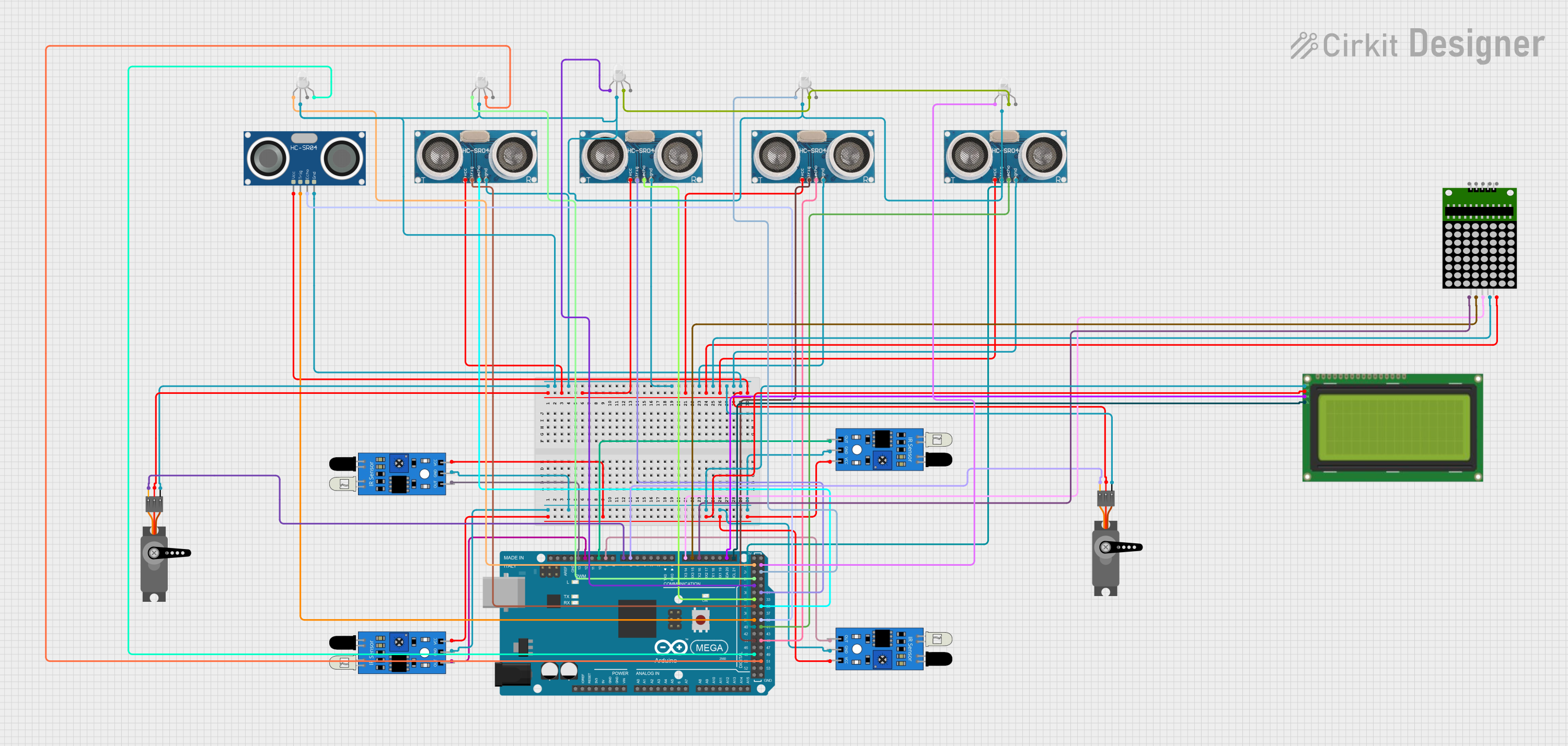
Circuit Documentation
Summary
The circuit is designed to function as a parking system, utilizing a variety of sensors, displays, and actuators to manage and indicate parking space availability. The core of the system is an Arduino Mega 2560, which interfaces with ultrasonic sensors, infrared (IR) sensors, an I2C LCD display, an 8x8 LED matrix, RGB LEDs, and servo motors. The ultrasonic sensors are used to detect the presence of vehicles, while the IR sensors provide additional input for the system. The LCD display and 8x8 matrix offer visual feedback, and the RGB LEDs serve as status indicators. The servo motors are likely used to control entry and exit barriers. The system is powered by a 5V supply, with ground connections distributed throughout the components.
Component List
- Lcd 20x4 i2c: A 20x4 character LCD display with an I2C interface for displaying information.
- Arduino Mega 2560: A microcontroller board based on the ATmega2560, with numerous digital and analog I/O pins.
- 8x8 matrix: An 8x8 LED matrix display for visual output.
- HC-SR04 Ultrasonic Sensor: An ultrasonic distance sensor that measures distance by emitting ultrasonic waves and measuring the reflection.
- Ultrasonic Sensor: Generic ultrasonic distance sensors similar to the HC-SR04.
- IR Sensor: Infrared sensors used for detecting the presence of objects or motion.
- Servo: A rotary actuator or motor that allows for precise control of angular position.
- RGB LED (Wokwi compatible): A light-emitting diode that can display multiple colors by mixing red, green, and blue light.
Wiring Details
Lcd 20x4 i2c
- GND: Connected to the ground net.
- 5v: Connected to the 5V power net.
- SCA: Connected to the SDA pin (D20/SDA) on the Arduino Mega 2560.
- SCL: Connected to the SCL pin (D21/SCL) on the Arduino Mega 2560.
Arduino Mega 2560
- Digital and PWM pins: Connected to various components such as the 8x8 matrix, servos, IR sensors, ultrasonic sensors, and RGB LEDs for control and data exchange.
- I2C pins (SDA, SCL): Used for communication with the I2C LCD display.
- 5V and GND pins: Provide power and ground to connected components.
8x8 matrix
- VCC: Connected to the 5V power net.
- DIN: Connected to pin D14/TX3 on the Arduino Mega 2560.
- CLK: Connected to pin D15/RX3 on the Arduino Mega 2560.
- CS: Connected to pin D16 PWM/TX2 on the Arduino Mega 2560.
- GND: Connected to the ground net.
HC-SR04 Ultrasonic Sensor
- VCC: Connected to the 5V power net.
- TRIG: Connected to pin D38 on the Arduino Mega 2560.
- ECHO: Connected to pin D39 on the Arduino Mega 2560.
- GND: Connected to the ground net.
Generic Ultrasonic Sensors
- +VCC: Connected to the 5V power net.
- Trigger: Connected to various digital pins on the Arduino Mega 2560 (D44, D40, D34, D31).
- Echo: Connected to various digital pins on the Arduino Mega 2560 (D45, D41, D35, D32).
- GND: Connected to the ground net.
IR Sensors
- Out: Connected to various PWM pins on the Arduino Mega 2560 (D9, D10, D12, D13).
- GND: Connected to the ground net.
- VCC: Connected to the 5V power net.
Servos
- GND: Connected to the ground net.
- VCC: Connected to the 5V power net.
- PWM: Connected to PWM pins on the Arduino Mega 2560 (D6, D7).
RGB LEDs (Wokwi compatible)
- R: Connected to various digital pins on the Arduino Mega 2560 (D22, D26, D28, D25, D23).
- G: Connected to digital pin D51 on the Arduino Mega 2560 and shared with other RGB LEDs.
- B: Connected to digital pin D48 on the Arduino Mega 2560.
- COM: Connected to the ground net.
Documented Code
/*
 * Arduino Sketch for Parking System
 * This code interfaces with multiple ultrasonic sensors, IR sensors, an LCD,
 * an 8x8 matrix display, RGB LEDs, and servos to create a parking system. The
 * system detects the presence of vehicles using ultrasonic and IR sensors,
 * displays information on the LCD and 8x8 matrix, controls servos for barriers,
 * and uses RGB LEDs for status indication.
 */

#include <Wire.h>
#include <LiquidCrystal_I2C.h>
#include <Servo.h>

// LCD setup
LiquidCrystal_I2C lcd(0x27, 20, 4);

// Servo setup
Servo servo1;
Servo servo2;

// Pin definitions
const int irSensor1Pin = 12;
const int irSensor2Pin = 13;
const int irSensor3Pin = 10;
const int irSensor4Pin = 9;
const int trigPin1 = 40;
const int echoPin1 = 41;
const int trigPin2 = 44;
const int echoPin2 = 45;
const int trigPin3 = 31;
const int echoPin3 = 32;
const int trigPin4 = 34;
const int echoPin4 = 35;
const int trigPin5 = 38;
const int echoPin5 = 39;
const int servo1Pin = 7;
const int servo2Pin = 6;
const int matrixDIN = 14;
const int matrixCLK = 15;
const int matrixCS = 16;
const int rgbLed1R = 22;
const int rgbLed2R = 26;
const int rgbLed3R = 28;
const int rgbLed4R = 25;
const int rgbLed5R = 23;
const int rgbLed1B = 48;
const int rgbLed2G = 51;

void setup() {
  // Initialize LCD
  lcd.begin();
  lcd.backlight();
  lcd.print("Parking System");

  // Initialize servos
  servo1.attach(servo1Pin);
  servo2.attach(servo2Pin);

  // Initialize IR sensors
  pinMode(irSensor1Pin, INPUT);
  pinMode(irSensor2Pin, INPUT);
  pinMode(irSensor3Pin, INPUT);
  pinMode(irSensor4Pin, INPUT);

  // Initialize ultrasonic sensors
  pinMode(trigPin1, OUTPUT);
  pinMode(echoPin1, INPUT);
  pinMode(trigPin2, OUTPUT);
  pinMode(echoPin2, INPUT);
  pinMode(trigPin3, OUTPUT);
  pinMode(echoPin3, INPUT);
  pinMode(trigPin4, OUTPUT);
  pinMode(echoPin4, INPUT);
  pinMode(trigPin5, OUTPUT);
  pinMode(echoPin5, INPUT);

  // Initialize 8x8 matrix
  pinMode(matrixDIN, OUTPUT);
  pinMode(matrixCLK, OUTPUT);
  pinMode(matrixCS, OUTPUT);

  // Initialize RGB LEDs
  pinMode(rgbLed1R, OUTPUT);
  pinMode(rgbLed2R, OUTPUT);
  pinMode(rgbLed3R, OUTPUT);
  pinMode(rgbLed4R, OUTPUT);
  pinMode(rgbLed5R, OUTPUT);
  pinMode(rgbLed1B, OUTPUT);
  pinMode(rgbLed2G, OUTPUT);
}

void loop() {
  // Main code to run repeatedly
  // Add your logic for parking system here
}

// Function to measure distance using ultrasonic sensor
long measureDistance(int trigPin, int echoPin) {
  digitalWrite(trigPin, LOW);
  delayMicroseconds(2);
  digitalWrite(trigPin, HIGH);
  delayMicroseconds(10);
  digitalWrite(trigPin, LOW);
  long duration = pulseIn(echoPin, HIGH);
  long distance = duration * 0.034 / 2;
  return distance;
}
This code is the main sketch for the Arduino Mega 2560, which controls the parking system. It includes initializations for the LCD, servos, IR sensors, ultrasonic sensors, 8x8 matrix, and RGB LEDs. The setup() function configures the pins and initializes the components, while the loop() function is intended to contain the main logic of the parking system, which is not provided in the code snippet. The measureDistance() function is a utility to measure distance using the ultrasonic sensors.