Cirkit Designer
Your all-in-one circuit design IDE
Home /
Project Documentation
Arduino-Controlled Smart Greenhouse System with Soil Moisture Sensing and Climate Control
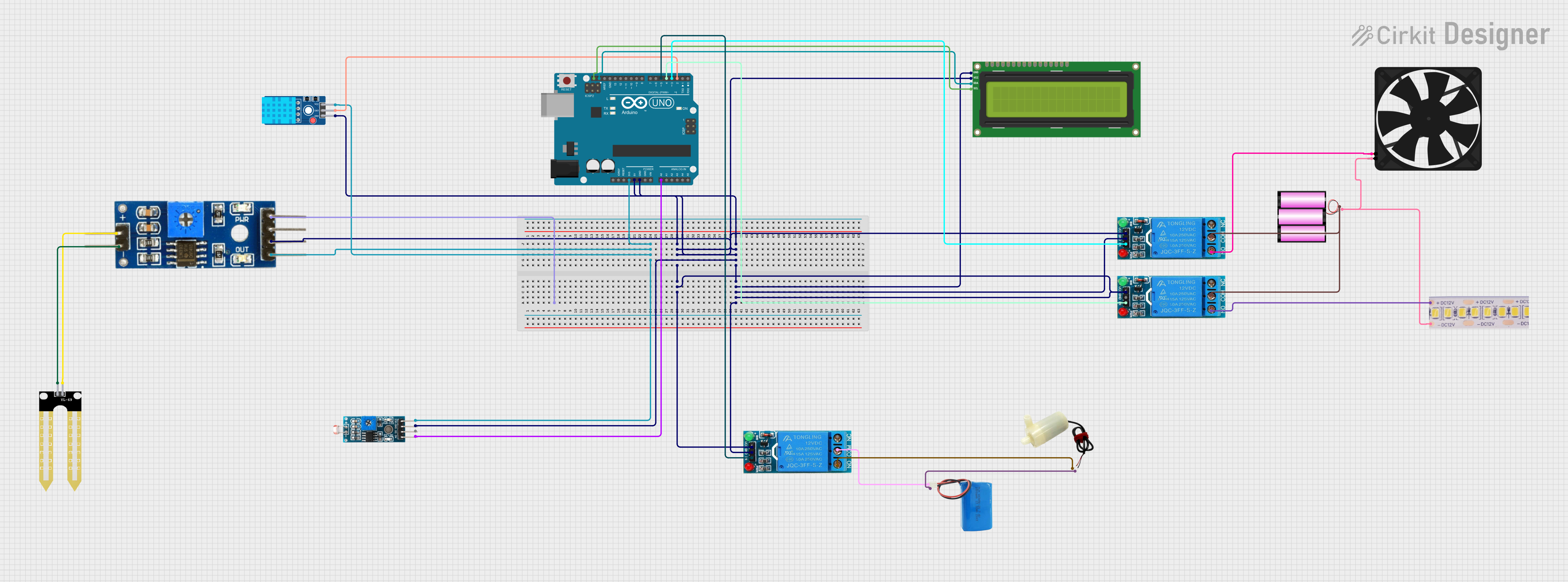
Greenhouse Control System Circuit Documentation
Summary
The Greenhouse Control System is designed to monitor and control various environmental parameters within a greenhouse setting. The system utilizes an Arduino UNO microcontroller to read sensor data and control actuators via relays. The sensors include a soil moisture module, a light-dependent resistor (LDR) module, and a DHT11 temperature and humidity sensor. Actuators in the system include a fan, a water pump, and a 12V white LED strip for lighting. The system's logic is programmed to activate the fan, water pump, and LED strip based on temperature, soil moisture, and ambient light levels, respectively.
Component List
- Module LDR: A light-dependent resistor module used to measure the intensity of light.
- Soil Moisture Module: A sensor module used to measure the moisture content of the soil.
- YL-69 Sonda: A probe that works in conjunction with the soil moisture module.
- Fan: An electric fan used to regulate air circulation and temperature.
- 12V White LED Strip: A strip of LEDs used to provide supplemental lighting.
- I2C LCD 16x2 Screen: A 16x2 character LCD display with an I2C interface for outputting sensor readings and system status.
- 5V Mini Water Pump: A small water pump used for irrigation purposes.
- Battery 12V: A 12-volt battery that powers the 12V components in the circuit.
- 12V Single Channel Relay: Electromechanical switches used to control high power devices with the Arduino's low power signals.
- 5V Battery: A 5-volt battery used to power the 5V components in the circuit.
- Arduino UNO: The main microcontroller board that controls the system.
- DHT11 Sensor V2: A sensor for measuring temperature and humidity.
Wiring Details
Module LDR
- VCC: Connected to Arduino UNO 3.3V.
- GND: Connected to common ground.
- DO: Not connected in this circuit.
- AO: Connected to Arduino UNO A0.
Soil Moisture Module
- VCC: Connected to Arduino UNO 3.3V.
- GND: Connected to common ground.
- Analog: Not connected in this circuit.
- Digital: Not connected in this circuit.
- Ground: Connected to common ground.
- Positive: Connected to YL-69 Sonda positive.
- Negative: Connected to YL-69 Sonda negative.
YL-69 Sonda
- +: Connected to Soil Moisture Module positive.
- -: Connected to Soil Moisture Module negative.
Fan
- 5V: Connected to NO (Normally Open) contact of a 12V Single Channel Relay.
- GND: Connected to common ground.
12V White LED Strip
- +12V: Connected to NO (Normally Open) contact of a 12V Single Channel Relay.
- GND: Connected to common ground.
I2C LCD 16x2 Screen
- SCL: Connected to Arduino UNO SCL.
- SDA: Connected to Arduino UNO SDA.
- VCC (5V): Connected to Arduino UNO 5V.
- GND: Connected to common ground.
5V Mini Water Pump
- Positive Pin: Connected to NO (Normally Open) contact of a 12V Single Channel Relay.
- Negative Pin: Connected to 5V Battery negative.
Battery 12V
- +: Connected to COM (Common) contacts of 12V Single Channel Relays.
- -: Connected to common ground.
12V Single Channel Relay
- NC (Normally Closed): Not connected in this circuit.
- COM (Common): Connected to 12V Battery positive.
- NO (Normally Open): Connected to Fan, 12V White LED Strip, and 5V Mini Water Pump.
- IN: Connected to Arduino UNO D3, D4, and D5 for control signals.
- GND: Connected to common ground.
- VCC: Connected to Arduino UNO 5V.
5V Battery
- Positive: Connected to COM (Common) contact of a 12V Single Channel Relay.
- Negative: Connected to common ground.
Arduino UNO
- 3.3V: Connected to VCC of Module LDR and Soil Moisture Module.
- 5V: Connected to VCC of I2C LCD 16x2 Screen and 12V Single Channel Relays.
- GND: Connected to common ground.
- Vin: Not connected in this circuit.
- A0: Connected to AO of Module LDR.
- A1-A5: Not connected in this circuit.
- SCL: Connected to SCL of I2C LCD 16x2 Screen.
- SDA: Connected to SDA of I2C LCD 16x2 Screen.
- AREF: Not connected in this circuit.
- D2: Connected to DAT of DHT11 Sensor V2.
- D3-D5: Connected to IN of 12V Single Channel Relays for control signals.
- D6-D13: Not connected in this circuit.
DHT11 Sensor V2
- GND: Connected to common ground.
- DAT: Connected to Arduino UNO D2.
- VCC: Connected to Arduino UNO 3.3V.
Documented Code
#include <Wire.h>
#include <LiquidCrystal_I2C.h>
#include <DHT.h>

// Define pin connections
#define DHTPIN 2              // DHT11 data pin connected to D2
#define DHTTYPE DHT11         // Defining the DHT sensor type as DHT11
#define SOIL_MOISTURE_PIN A0  // Soil moisture sensor connected to A0
#define LDR_PIN A1            // LDR sensor connected to A1
#define RELAY_FAN_PIN 3       // Relay controlling fan connected to D3
#define RELAY_PUMP_PIN 4      // Relay controlling water pump connected to D4
#define RELAY_LED_PIN 5       // Relay controlling LED strip connected to D5

// Initialize DHT sensor with the correct pin and type
DHT dht(DHTPIN, DHTTYPE);

// Initialize LCD (I2C address, columns, rows)
LiquidCrystal_I2C lcd(0x27, 16, 2);

void setup() {
  // Start serial communication for debugging
  Serial.begin(9600);

  // Start DHT sensor
  dht.begin();

  // Initialize LCD display (16 columns, 2 rows)
  lcd.begin(16, 2);
  lcd.backlight();

  // Set pin modes
  pinMode(SOIL_MOISTURE_PIN, INPUT);
  pinMode(LDR_PIN, INPUT);
  pinMode(RELAY_FAN_PIN, OUTPUT);
  pinMode(RELAY_PUMP_PIN, OUTPUT);
  pinMode(RELAY_LED_PIN, OUTPUT);

  // Ensure all relays (fan, pump, LED) are off initially
  digitalWrite(RELAY_FAN_PIN, LOW);
  digitalWrite(RELAY_PUMP_PIN, LOW);
  digitalWrite(RELAY_LED_PIN, LOW);

  // Welcome message on LCD
  lcd.setCursor(0, 0);
  lcd.print("Greenhouse Sys");
  delay(2000);
  lcd.clear();
}

void loop() {
  // Read and map soil moisture value to percentage
  int soilMoistureValue = analogRead(SOIL_MOISTURE_PIN);
  int soilMoisturePercent = map(soilMoistureValue, 1023, 0, 0, 100);

  // Read and map light level (LDR) to percentage
  int ldrValue = analogRead(LDR_PIN);
  int lightLevel = map(ldrValue, 0, 1023, 0, 100);

  // Read temperature and humidity values from DHT11 sensor
  float humidity = dht.readHumidity();
  float temperature = dht.readTemperature();

  // Display temperature and humidity on LCD
  lcd.setCursor(0, 0);
  lcd.print("Temp: ");
  lcd.print(temperature);
  lcd.print("C Hum: ");
  lcd.print(humidity);
  lcd.print("%");

  // Display soil moisture and light level on LCD
  lcd.setCursor(0, 1);
  lcd.print("Soil: ");
  lcd.print(soilMoisturePercent);
  lcd.print("% Light: ");
  lcd.print(lightLevel);
  lcd.print("%");

  // Control fan based on temperature
  if (temperature > 30) {
    digitalWrite(RELAY_FAN_PIN, HIGH);  // Turn on fan
  } else {
    digitalWrite(RELAY_FAN_PIN, LOW);   // Turn off fan
  }

  // Control water pump based on soil moisture
  if (soilMoisturePercent < 30) {
    digitalWrite(RELAY_PUMP_PIN, HIGH);  // Turn on water pump
  } else {
    digitalWrite(RELAY_PUMP_PIN, LOW);   // Turn off water pump
  }

  // Control LED strip based on light level
  if (lightLevel < 40) {
    digitalWrite(RELAY_LED_PIN, HIGH);  // Turn on LED strip