
Arduino-Controlled 28BYJ-48 Stepper Motor with nMOS Transistors
View and Edit Project In Cirkit Designer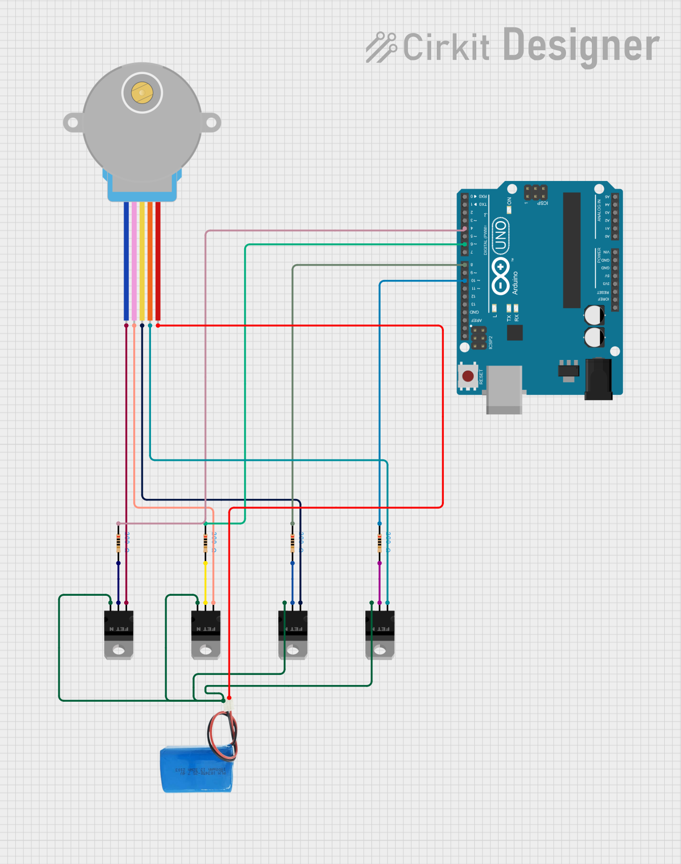
Circuit Documentation
Summary
This circuit is designed to control a 28BYJ-48 stepper motor using an Arduino UNO and four nMOS transistors. The transistors are connected to the Arduino's digital pins through resistors, and the motor's coils are connected to the transistors' gates. The Arduino sequentially activates the transistors to drive the stepper motor. The circuit is powered by a 5V battery.
Component List
28BYJ-48 Stepper Motor
- Pins: BLUE, PINK, YELLOW, ORANGE, RED
- Description: A small stepper motor used for precise control of angular position.
5V Battery
- Pins: positive, negative
- Description: Provides power to the circuit.
nMOS Transistor (MOSFET)
- Pins: gate, drain, source
- Description: Used to switch the current to the stepper motor coils.
Resistor
- Pins: pin1, pin2
- Description: Limits the current to the transistors.
- Properties: Resistance = 200 Ohms
Arduino UNO
- Pins: UNUSED, IOREF, Reset, 3.3V, 5V, GND, Vin, A0, A1, A2, A3, A4, A5, SCL, SDA, AREF, D13, D12, D11, D10, D9, D8, D7, D6, D5, D4, D3, D2, D1, D0
- Description: Microcontroller used to control the stepper motor.
Wiring Details
28BYJ-48 Stepper Motor
- BLUE connected to gate of nMOS Transistor (MOSFET)
- PINK connected to gate of nMOS Transistor (MOSFET)
- YELLOW connected to gate of nMOS Transistor (MOSFET)
- ORANGE connected to gate of nMOS Transistor (MOSFET)
- RED connected to positive of 5V Battery
5V Battery
- positive connected to RED of 28BYJ-48 Stepper Motor
- negative connected to source of all nMOS Transistors (MOSFET)
nMOS Transistor (MOSFET)
- gate connected to:
- BLUE of 28BYJ-48 Stepper Motor
- PINK of 28BYJ-48 Stepper Motor
- YELLOW of 28BYJ-48 Stepper Motor
- ORANGE of 28BYJ-48 Stepper Motor
- drain connected to:
- pin2 of Resistor
- pin2 of Resistor
- pin2 of Resistor
- pin2 of Resistor
- source connected to negative of 5V Battery
Resistor
- pin1 connected to:
- D4 of Arduino UNO
- D6 of Arduino UNO
- D8 of Arduino UNO
- D10 of Arduino UNO
- pin2 connected to:
- drain of nMOS Transistor (MOSFET)
- drain of nMOS Transistor (MOSFET)
- drain of nMOS Transistor (MOSFET)
- drain of nMOS Transistor (MOSFET)
Arduino UNO
- D4 connected to pin1 of Resistor
- D6 connected to pin1 of Resistor
- D8 connected to pin1 of Resistor
- D10 connected to pin1 of Resistor
Code Documentation
/*
 * This Arduino sketch controls a 28BYJ-48 stepper motor using four nMOS
 * transistors. The transistors are connected to the Arduino's digital pins
 * through resistors, and the motor's coils are connected to the transistors'
 * gates. The Arduino sequentially activates the transistors to drive the
 * stepper motor.
 */

// Pin definitions
const int pinD4 = 4;
const int pinD6 = 6;
const int pinD8 = 8;
const int pinD10 = 10;

// Stepper motor sequence
const int stepSequence[4] = {pinD4, pinD6, pinD8, pinD10};
const int numSteps = 4;

void setup() {
  // Initialize the digital pins as outputs
  for (int i = 0; i < numSteps; i++) {
    pinMode(stepSequence[i], OUTPUT);
  }
}

void loop() {
  // Step the motor
  for (int i = 0; i < numSteps; i++) {
    // Activate the current transistor
    digitalWrite(stepSequence[i], HIGH);
    // Wait for a short period to allow the motor to move
    delay(100); // Adjust delay for speed control
    // Deactivate the current transistor
    digitalWrite(stepSequence[i], LOW);
  }
}
This code initializes the digital pins connected to the transistors as outputs and sequentially activates them to drive the stepper motor. The delay between steps can be adjusted to control the speed of the motor.