
Arduino and ESP8266 Based Environmental Monitoring System with LoRa Communication
View and Edit Project In Cirkit Designer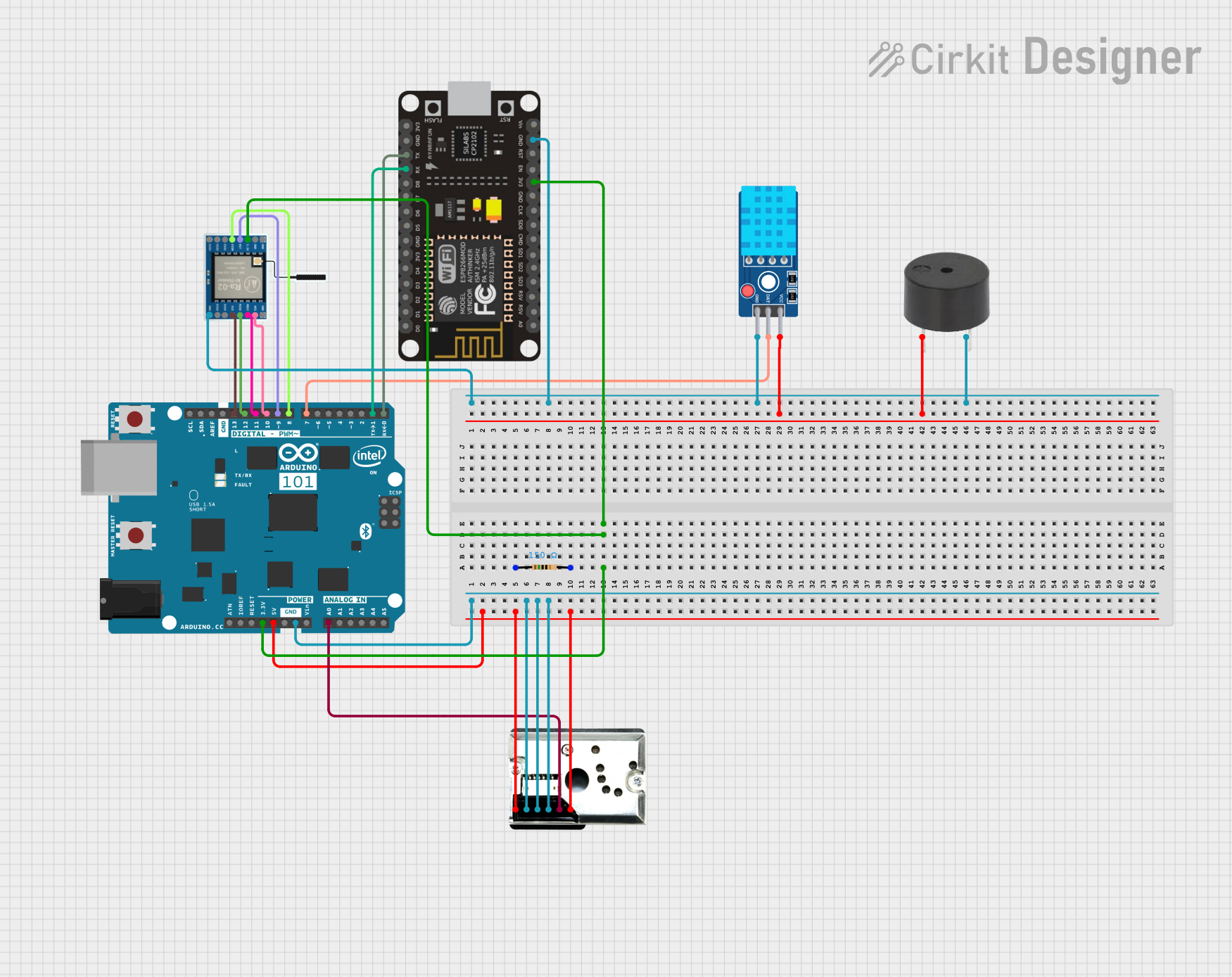
Circuit Documentation
Summary
The circuit in question is a multifunctional system designed to interface with various sensors and communication modules. It includes an Arduino 101 microcontroller as the central processing unit, interfacing with a DHT11 temperature and humidity sensor, a GP2Y1010AU0F dust sensor, a LoRa Ra-02 SX1278 module for long-range communication, an ESP8266 NodeMCU for Wi-Fi capabilities, and a buzzer for audible alerts. The circuit is powered by a 3.3V supply, which is distributed to the necessary components, and a 5V supply for specific sensors. The Arduino 101 also communicates with the ESP8266 NodeMCU via serial connection for data exchange.
Component List
DHT11 Sensor V2
- Description: A temperature and humidity sensor with a digital output.
- Pins: GND, DAT, VCC
Arduino 101
- Description: A microcontroller board based on the Intel Curie Module, designed for IoT applications.
- Pins: A5/SCL, A4/SDA, AREF, GND, D13/SCK, D12/MISO, D11 PWM/MOSI, D10 PWM/SS, D9 PWM, D8, D7, D6 PWM, D5 PWM, D4, D3 PWM, D2, D1/TX, D0/RX, AIN, ioref, RESET, 3V3, 5V, VIN, A0, A1, A2, A3, ICSP MISO, ICSP SCK, ICSP MOSI
GP2Y1010AU0F
- Description: An optical air quality sensor designed to sense dust particles.
- Pins: VCC, Vout, S-GND, LED, LED-GND, V-LED
Resistor
- Description: A passive two-terminal electrical component that implements electrical resistance as a circuit element.
- Properties: 150 Ohms
LoRa Ra-02 SX1278
- Description: A long-range transceiver module based on the SX1278 from Semtech.
- Pins: GND, NSS, MOSI, MISO, SCK, D105, DI04, 3.3V, RST, DI00, DI01, D102, DI03
ESP8266 NodeMCU
- Description: A low-cost Wi-Fi microchip with full TCP/IP stack and microcontroller capability.
- Pins: D0, D1, D2, D3, D4, 3V3, GND, D5, D6, D7, D8, RX, TX, A0, RSV, SD3, SD2, SD1, CMD, SD0, CLK, EN, RST, VIN
Buzzer
- Description: An audio signaling device that can be mechanical, electromechanical, or piezoelectric.
- Pins: PIN, GND
Wiring Details
DHT11 Sensor V2
- GND connected to common ground.
- DAT connected to Arduino 101 (D7).
- VCC connected to Arduino 101 (5V).
Arduino 101
- 3V3 connected to ESP8266 NodeMCU (3V3) and LoRa Ra-02 SX1278 (3.3V).
- GND connected to common ground.
- 5V connected to GP2Y1010AU0F (V-LED and VCC).
- D13/SCK, D12/MISO, D11 PWM/MOSI, D10 PWM/SS, D9 PWM, and D8 connected to corresponding pins on LoRa Ra-02 SX1278 for SPI communication.
- D1/TX connected to ESP8266 NodeMCU (RX).
- D0/RX connected to ESP8266 NodeMCU (TX).
- A0 connected to GP2Y1010AU0F (Vout).
GP2Y1010AU0F
- VCC and V-LED connected to Arduino 101 (5V).
- Vout connected to Arduino 101 (A0).
- LED, LED-GND, and S-GND connected to common ground.
LoRa Ra-02 SX1278
- 3.3V connected to Arduino 101 (3V3).
- GND connected to common ground.
- NSS, MOSI, MISO, SCK, RST, and DI00 connected to corresponding pins on Arduino 101 for SPI communication and control.
ESP8266 NodeMCU
- 3V3 connected to Arduino 101 (3V3).
- GND connected to common ground.
- RX connected to Arduino 101 (D1/TX).
- TX connected to Arduino 101 (D0/RX).
Buzzer
- PIN connected to DHT11 Sensor V2 (VCC).
- GND connected to common ground.
Documented Code
Arduino 101 Code
#include <Wire.h>
#include <LiquidCrystal_I2C.h>
#include <Adafruit_Sensor.h>
#include <DHT.h>
#include <RTClib.h>
#include <SPI.h>
#include <LoRa.h>
#include <SoftwareSerial.h>

// LCD Setup
LiquidCrystal_I2C lcd(0x27, 16, 2);

// DHT Sensor Setup
#define DHTPIN 7
#define DHTTYPE DHT11
DHT dht(DHTPIN, DHTTYPE);

// Dust Sensor Setup
#define measurePin A0
#define ledPower 7
int samplingTime = 280;
int deltaTime = 40;
int sleepTime = 9680;
float voMeasured = 0;
float calcVoltage = 0;
float dustDensity = 0;

// RTC Setup
RTC_DS1307 rtc;

// LoRa and ESP8266 Setup
#define NSS  10
#define RST  9
#define DIO0 8
SoftwareSerial espSerial(0, 1);  // RX, TX for ESP8266

// Buzzer Setup
const int buzzer = 9;

// Variables
int num = 0;

void setup() {
  Serial.begin(115200);

  // LCD Init
  lcd.init();
  lcd.backlight();

  // DHT Init
  dht.begin();

  // RTC Init
  if (!rtc.begin()) {
    Serial.println("Couldn't find RTC");
    while (1);
  }

  // LoRa Init
  LoRa.setPins(NSS, RST, DIO0);
  if (!LoRa.begin(433E6)) {
    Serial.println("Starting LoRa failed!");
    while (1);
  }

  // ESP8266 Init
  espSerial.begin(9600);

  // Buzzer Init
  pinMode(buzzer, OUTPUT);

  // Dust Sensor Init
  pinMode(ledPower, OUTPUT);

  // Initial Display on LCD
  lcd.setCursor(0, 0);
  lcd.print("System Starting");
  delay(2000);
}

void loop() {
  // Time from RTC
  DateTime now = rtc.now();

  // Temperature and Humidity from DHT
  float h = dht.readHumidity();
  float t = dht.readTemperature();

  // Dust Sensor Reading
  digitalWrite(ledPower, LOW);
  delayMicroseconds(samplingTime);
  voMeasured = analogRead(measurePin);
  delayMicroseconds(deltaTime);
  digitalWrite(ledPower, HIGH);
  delayMicroseconds(sleepTime);
  calcVoltage = voMeasured * (5.0 / 1024.0);
  dustDensity = 170 * calcVoltage - 0.1;

  // Buzzer Alert
  tone(buzzer, 1000);
  delay(1000);
  noTone(buzzer);
  delay(1000);

  // Display on LCD
  lcd.clear();
  lcd.setCursor(0, 0);
  lcd.print("Time: ");
  lcd.print(now.hour());
  lcd.print(":");
  lcd.print(now.minute());
  lcd.print(":");
  lcd.print(now.second());

  lcd.setCursor(0, 1);
  lcd.print("Temp: ");
  lcd.print(t);
  lcd.print(" C");

  lcd.setCursor(0, 2);
  lcd.print("Humidity: ");
  lcd.print(h);
  lcd.print(" %");

  lcd.setCursor(0, 3);
  lcd.print("Dust: ");
  lcd.print(dustDensity);

  // LoRa Communication
  LoRa.beginPacket();
  LoRa.print("Data: Temp=");
  LoRa.print(t);
  LoRa.print(", Humidity=");
  LoRa.print(h);
  LoRa.print(", Dust=");
  LoRa.print(dustDensity);
  LoRa.endPacket();

  // ESP8266 Data Reception
  if (espSerial.available()) {
    String data = espSerial.readString();
    Serial.println("Data from ESP8266: " + data);
  }

  // Update every 2 seconds
  delay(2000);
}
DHT11 Sensor V2 Code
void setup() {
  // put your setup code here, to run