
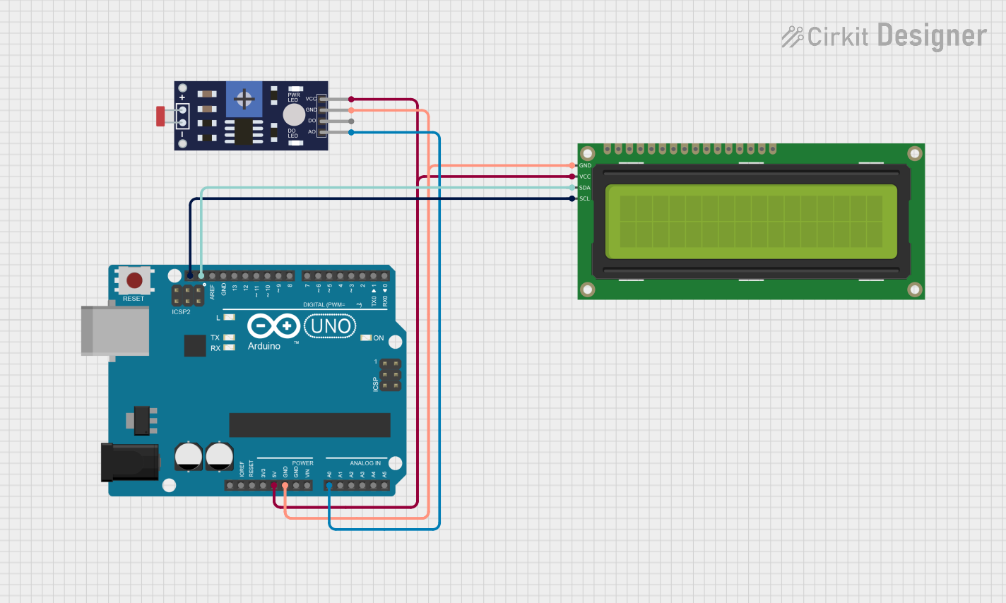
Circuit Documentation
Summary
This circuit is designed to measure ambient light levels using a Photoresistor (LDR) sensor and display the readings on a 16x2 I2C LCD. The Arduino UNO microcontroller processes the sensor data and controls the LCD to provide real-time feedback on the light intensity in the environment.
Component List
Photoresistor (LDR) Sensor
- Description: A light-dependent resistor that changes its resistance based on the amount of light falling on it.
- Purpose: To measure the ambient light levels and provide an analog output to the Arduino.
Arduino UNO
- Description: A microcontroller board based on the ATmega328P.
- Purpose: To read the sensor data, process it, and control the LCD display.
16x2 I2C LCD
- Description: A liquid crystal display that can show 16 characters on 2 lines, controlled via I2C communication.
- Purpose: To display the light intensity readings from the LDR sensor.
Wiring Details
Photoresistor (LDR) Sensor
VCC: Connected to the 5V pin of the Arduino UNO.
GND: Connected to the GND pin of the Arduino UNO.
AO: Connected to the A0 pin of the Arduino UNO for analog readings.
Arduino UNO
5V: Connected to the VCC pin of the Photoresistor (LDR) Sensor and the VCC pin of the 16x2 I2C LCD.
GND: Connected to the GND pin of the Photoresistor (LDR) Sensor and the GND pin of the 16x2 I2C LCD.
A0: Connected to the AO pin of the Photoresistor (LDR) Sensor for reading the analog value.
SCL: Connected to the SCL pin of the 16x2 I2C LCD for I2C communication.
SDA: Connected to the SDA pin of the 16x2 I2C LCD for I2C communication.
16x2 I2C LCD
VCC: Connected to the 5V pin of the Arduino UNO.
GND: Connected to the GND pin of the Arduino UNO.
SCL: Connected to the SCL pin of the Arduino UNO for I2C communication.
SDA: Connected to the SDA pin of the Arduino UNO for I2C communication.
Documented Code
#include <Wire.h>
#include <LiquidCrystal_I2C.h>

// Initialize the library with the I2C address for the LCD
LiquidCrystal_I2C lcd(0x27, 16, 2); // 0x27 is a common I2C address for these displays

#define LDR_PIN A0

// LDR Characteristics
const float GAMMA = 0.7;
const float RL10 = 50;

void setup() {
    pinMode(8, OUTPUT);
    pinMode(9, OUTPUT);
    digitalWrite(8, LOW);
    digitalWrite(9, HIGH);

    pinMode(LDR_PIN, INPUT);

    lcd.begin(16, 2); // Initialize the LCD with 16 columns and 2 rows
    lcd.backlight(); // Turn on the backlight
}

void loop() {
    int analogValue = analogRead(A0);
    float voltage = analogValue / 1024.0 * 5;
    float resistance = 2000 * voltage / (1 - voltage / 5);
    float lux = pow(RL10 * 1e3 * pow(10, GAMMA) / resistance, (1 / GAMMA));

    lcd.setCursor(2, 0);
    lcd.print("Room: ");
    if (lux > 50) {
        lcd.print("Light!");
    } else {
        lcd.print("Dark  ");
    }

    lcd.setCursor(0, 1);
    lcd.print("Lux: ");
    lcd.print(lux);
    lcd.print("          ");

    delay(100);
}
This code initializes the LCD and continuously reads the light level from the LDR sensor, displaying the results on the LCD. The program distinguishes between light and dark conditions based on the lux value calculated from the sensor readings.