ESP32-CAM Based Wi-Fi Controlled Face Recognition Door Lock
Circuit Documentation
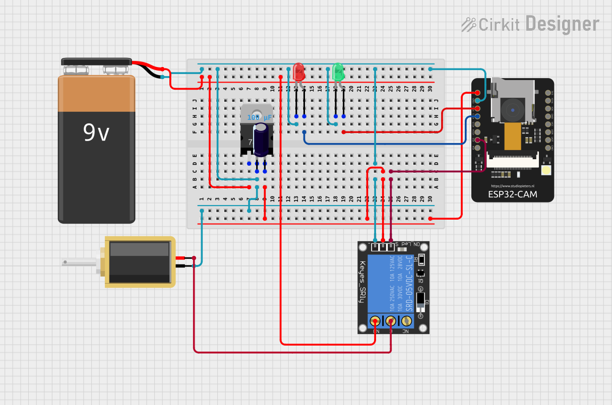
Summary
The circuit in question is designed to incorporate an ESP32-CAM module, which is a small camera module with the ESP32-S chip that provides Wi-Fi and Bluetooth connectivity. The circuit also includes a solenoid, a voltage regulator, two LEDs (green and red), a 1-channel relay, a 9V battery, and an electrolytic capacitor. The purpose of the circuit is not explicitly stated, but given the components, it could be used for a security system with camera-based face recognition to control access through a solenoid lock.
Component List
ESP32-CAM
- Description: A small-sized ESP32-based module with a camera and Wi-Fi/Bluetooth capabilities.
- Pins: 5V, GND, IO12, IO13, IO15, IO14, IO2, IO4, VOT, VOR, VCC, IO0, IO16, 3V3
Solenoid
- Description: An electromechanical device used for locking or unlocking a mechanism.
- Pins: pin1, pin2
Voltage Regulator (V_REG_LD1117VXX)
- Description: A component used to maintain a constant voltage level.
- Pins: GND, OUT, IN
LED: Two Pin (green)
- Description: A green LED used for indicating status or events.
- Pins: cathode, anode
LED: Two Pin (red)
- Description: A red LED used for indicating status or events.
- Pins: cathode, anode
1-Channel Relay (5V 10A)
- Description: An electrically operated switch that allows you to control a high power circuit with a low power signal.
- Pins: NC, signal, C, power, NO, ground
9V Battery
- Description: A standard 9V battery used to provide power to the circuit.
- Pins: -, +
Electrolytic Capacitor
- Description: A capacitor used to filter out voltage spikes and smooth the power supply.
- Pins: -, +
- Properties: Capacitance - 0.0001 Farads
Wiring Details
ESP32-CAM
- 5V connected to the V_REG_LD1117VXX OUT pin, 1-Channel Relay power pin, and Electrolytic Capacitor + pin.
- GND connected to the common ground net, which includes Solenoid pin1, V_REG_LD1117VXX GND pin, 9V Battery -, both LED cathodes, 1-Channel Relay ground pin, and Electrolytic Capacitor - pin.
- IO12 connected to the green LED anode.
- IO13 connected to the red LED anode.
- IO2 connected to the 1-Channel Relay signal pin.
Solenoid
- pin1 connected to the common ground net.
- pin2 connected to the 1-Channel Relay C pin.
Voltage Regulator (V_REG_LD1117VXX)
- IN connected to the 9V Battery + pin.
- OUT connected to the common ground net.
- GND connected to the 1-Channel Relay NO pin.
LED: Two Pin (green)
- cathode connected to the common ground net.
- anode connected to the ESP32-CAM IO12 pin.
LED: Two Pin (red)
- cathode connected to the common ground net.
- anode connected to the ESP32-CAM IO13 pin.
1-Channel Relay (5V 10A)
- NC not connected.
- signal connected to the ESP32-CAM IO2 pin.
- C connected to the Solenoid pin2.
- power connected to the V_REG_LD1117VXX OUT pin.
- NO connected to the V_REG_LD1117VXX GND pin.
- ground connected to the common ground net.
9V Battery
- connected to the common ground net.
- connected to the V_REG_LD1117VXX IN pin.
Electrolytic Capacitor
- connected to the common ground net.
- connected to the ESP32-CAM 5V pin.
Documented Code
The code provided is for the ESP32-CAM module and includes several files:
CameraFaceRecognitionDoorLock.ino
This is the main Arduino sketch file for the ESP32-CAM. It initializes the camera, connects to Wi-Fi, and starts a web server to stream the camera feed. It also includes logic for face recognition and controlling a relay based on the recognition result.
documentation.txt
This file appears to be a placeholder for additional documentation.
index_ov2640.html.gz
This is a gzipped HTML file that serves as the web interface for the camera stream. It likely contains the UI elements for the camera's web server.
camera_pins.h
This header file defines the pin assignments for the camera module, which vary depending on the specific model of the camera being used.
app_httpd.h
This header file contains the HTTP server logic for the ESP32-CAM. It defines the endpoints for the web server, including the stream, capture, and command endpoints. It also includes the logic for handling face detection and recognition.
The code is designed to be uploaded to the ESP32-CAM module, which then serves a web page that can be accessed to view the camera feed and control the device's functionality. The face recognition feature is used to detect and recognize faces, which can then trigger the relay to lock or unlock a door, indicated by the red and green LEDs.