
Arduino Mega 2560 Battery-Powered Robotic System with Multiple Sensors and Motor Control
View and Edit Project In Cirkit Designer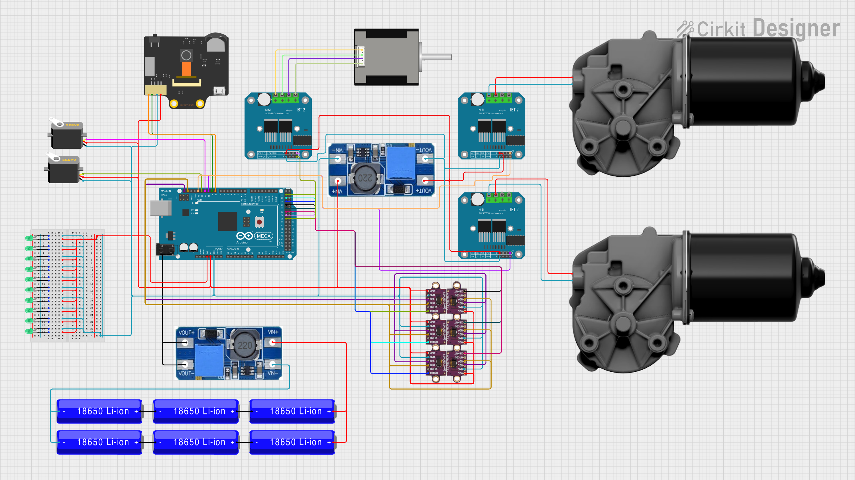
Circuit Documentation
Summary
This document provides a detailed overview of a circuit that includes various components such as LEDs, a microcontroller (Arduino Mega 2560), sensors, motors, and power converters. The circuit is designed to perform specific tasks as defined by the embedded code running on the microcontroller.
Component List
18650 Li-ion Battery
- Description: Rechargeable lithium-ion battery.
- Pins: -, +
Arduino Mega 2560
- Description: Microcontroller board based on the ATmega2560.
- Pins: IOREF, RESET, 3V3, 5V, GND, VIN, A0-A15, D0-D53, AREF, SDA, SCL
Step Up Boost Power Converter, Adjustable Voltage Regulator
- Description: Boost converter to step up voltage.
- Pins: VOUT+, VOUT-, VIN+, VIN-
Wire Connector
- Description: Connector for wiring.
- Pins: +, -
DC Worm Gear Motor
- Description: Motor with worm gear for high torque applications.
- Pins: Motor+, Motor-
Servo
- Description: Servo motor for precise control.
- Pins: gnd, vcc, pulse
LED: Two Pin (green)
- Description: Green LED.
- Pins: cathode, anode
Huskylens
- Description: AI vision sensor.
- Pins: SDA, SCL, GND, VCC
Nema 17 42-STH48
- Description: Stepper motor.
- Pins: A2 (black), A1 Green, B2 Red, B1 Blue
BTS7960 Motor Driver
- Description: High current motor driver.
- Pins: Pin 1-Pin 12
VL53L0XV2
- Description: Time-of-Flight distance sensor.
- Pins: vcc, GND, scl, SDA, SPI01, XSHUT
Wiring Details
18650 Li-ion Battery
- + connected to:
- - of another 18650 Li-ion Battery
- VIN+ of Step Up Boost Power Converter, Adjustable Voltage Regulator
- - connected to:
- + of another 18650 Li-ion Battery
- VIN- of Step Up Boost Power Converter, Adjustable Voltage Regulator
Arduino Mega 2560
- GND connected to:
- GND of VL53L0XV2
- GND of Huskylens
- gnd of Servo
- 3V3 connected to:
- cathode of multiple LEDs
- 5V connected to:
- vcc of VL53L0XV2
- VCC of Huskylens
- vcc of Servo
- D8 PWM connected to:
- SDA of Huskylens
- D9 PWM connected to:
- SCL of Huskylens
- D10 PWM connected to:
- Pin 8 of BTS7960 Motor Driver
- D11 PWM connected to:
- pulse of Servo
- D12 PWM connected to:
- pulse of another Servo
- D13 PWM connected to:
- Pin 8 of another BTS7960 Motor Driver
- SDA connected to:
- SDA of multiple VL53L0XV2 sensors
- SCL connected to:
- scl of multiple VL53L0XV2 sensors
- D36 connected to:
- Pin 4 of BTS7960 Motor Driver
- D34 connected to:
- Pin 8 of BTS7960 Motor Driver
- D32 connected to:
- XSHUT of VL53L0XV2
- D30 connected to:
- XSHUT of another VL53L0XV2
- D28 connected to:
- XSHUT of another VL53L0XV2
- D26 connected to:
- XSHUT of another VL53L0XV2
- D24 connected to:
- XSHUT of another VL53L0XV2
- D22 connected to:
- XSHUT of another VL53L0XV2
Step Up Boost Power Converter, Adjustable Voltage Regulator
- VIN+ connected to:
- + of 18650 Li-ion Battery
- VIN- connected to:
- - of 18650 Li-ion Battery
- VOUT+ connected to:
- + of Wire Connector
- VOUT- connected to:
- - of Wire Connector
Wire Connector
- + connected to:
- VOUT+ of Step Up Boost Power Converter, Adjustable Voltage Regulator
DC Worm Gear Motor
- Motor+ connected to:
- Pin 11 of BTS7960 Motor Driver
- Motor- connected to:
- Pin 12 of BTS7960 Motor Driver
Servo
- gnd connected to:
- GND of Arduino Mega 2560
- vcc connected to:
- 5V of Arduino Mega 2560
- pulse connected to:
- D11 PWM of Arduino Mega 2560
LED: Two Pin (green)
- anode connected to:
- anode of multiple LEDs
- cathode connected to:
- 3V3 of Arduino Mega 2560
Huskylens
- SDA connected to:
- D8 PWM of Arduino Mega 2560
- SCL connected to:
- D9 PWM of Arduino Mega 2560
- GND connected to:
- GND of Arduino Mega 2560
- VCC connected to:
- 5V of Arduino Mega 2560
Nema 17 42-STH48
- A2 (black) connected to:
- Pin 12 of BTS7960 Motor Driver
- A1 Green connected to:
- Pin 11 of BTS7960 Motor Driver
- B2 Red connected to:
- Pin 10 of BTS7960 Motor Driver
- B1 Blue connected to:
- Pin 9 of BTS7960 Motor Driver
BTS7960 Motor Driver
- Pin 1 connected to:
- Pin 1 of another BTS7960 Motor Driver
- VOUT- of Step Up Boost Power Converter, Adjustable Voltage Regulator
- Pin 4 connected to:
- D36 of Arduino Mega 2560
- Pin 5 connected to:
- Pin 5 of another BTS7960 Motor Driver
- VOUT+ of Step Up Boost Power Converter, Adjustable Voltage Regulator
- Pin 8 connected to:
- D10 PWM of Arduino Mega 2560
- Pin 11 connected to:
- Motor+ of DC Worm Gear Motor
- Pin 12 connected to:
- Motor- of DC Worm Gear Motor
VL53L0XV2
- vcc connected to:
- 5V of Arduino Mega 2560
- GND connected to:
- GND of Arduino Mega 2560
- scl connected to:
- SCL of Arduino Mega 2560
- SDA connected to:
- SDA of Arduino Mega 2560
- XSHUT connected to:
- D32 of Arduino Mega 2560
Documented Code
Arduino Mega 2560 Code
void setup() {
  // put your setup code here, to run once:

}

void loop() {
  // put your main code here, to run repeatedly:

}
Additional Documentation
// No additional documentation provided.
This document provides a comprehensive overview of the circuit, including the components used, their connections, and the embedded code running on the Arduino Mega 2560.