
Circuit Documentation
Summary of the Circuit
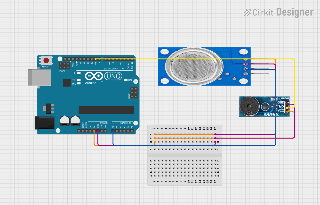
This circuit consists of an Arduino UNO microcontroller, an MQ135 gas sensor, and a Buzzer Module. The Arduino UNO serves as the central processing unit, controlling the sensor readings and the buzzer's activation based on the gas concentration levels detected by the MQ135 sensor. The MQ135 sensor is used for monitoring air quality by detecting various gases in the environment. The Buzzer Module is used as an audible alert system that can be triggered by the Arduino UNO when certain conditions are met, such as when the gas concentration exceeds a predefined threshold.
Component List
Arduino UNO
- Description: A microcontroller board based on the ATmega328P.
- Purpose: Acts as the central controller for the circuit, reading sensor data and controlling the buzzer.
- Pins: UNUSED, IOREF, Reset, 3.3V, 5V, GND, Vin, Analog Pins (A0-A5), SCL, SDA, AREF, Digital Pins (D0-D13).
MQ135 Gas Sensor
- Description: A sensor for detecting a wide range of gases, including NH3, NOx, alcohol, benzene, smoke, and CO2.
- Purpose: Monitors the air quality and provides analog output corresponding to the concentration of gases.
- Pins: VCC, GND, A0 (Analog Output), D0 (Digital Output).
Buzzer Module
- Description: An electronic buzzer that produces sound when powered.
- Purpose: Provides an audible alert when triggered by the Arduino UNO.
- Pins: GND, Vcc, I/O.
Wiring Details
Arduino UNO
- 5V connected to:
- MQ135 VCC
- Buzzer Module Vcc
- GND connected to:
- MQ135 GND
- Buzzer Module GND
- A0 connected to MQ135 A0 (Analog Output)
- D9 connected to Buzzer Module I/O
MQ135 Gas Sensor
- VCC connected to Arduino UNO 5V
- GND connected to Arduino UNO GND
- A0 connected to Arduino UNO A0
Buzzer Module
- Vcc connected to Arduino UNO 5V
- GND connected to Arduino UNO GND
- I/O connected to Arduino UNO D9
Documented Code
The following code is for the Arduino UNO microcontroller:
void setup() {
  // put your setup code here, to run once:

}

void loop() {
  // put your main code here, to run repeatedly:

}
The code provided is a template and does not contain any functional implementation. To complete the circuit's functionality, the setup function should be configured to initialize the sensor and buzzer pins, and the loop function should contain the logic for reading the sensor data, processing it, and activating the buzzer under certain conditions.