
Arduino-Controlled NeoPixel LED Display with Voltage Regulation
View and Edit Project In Cirkit Designer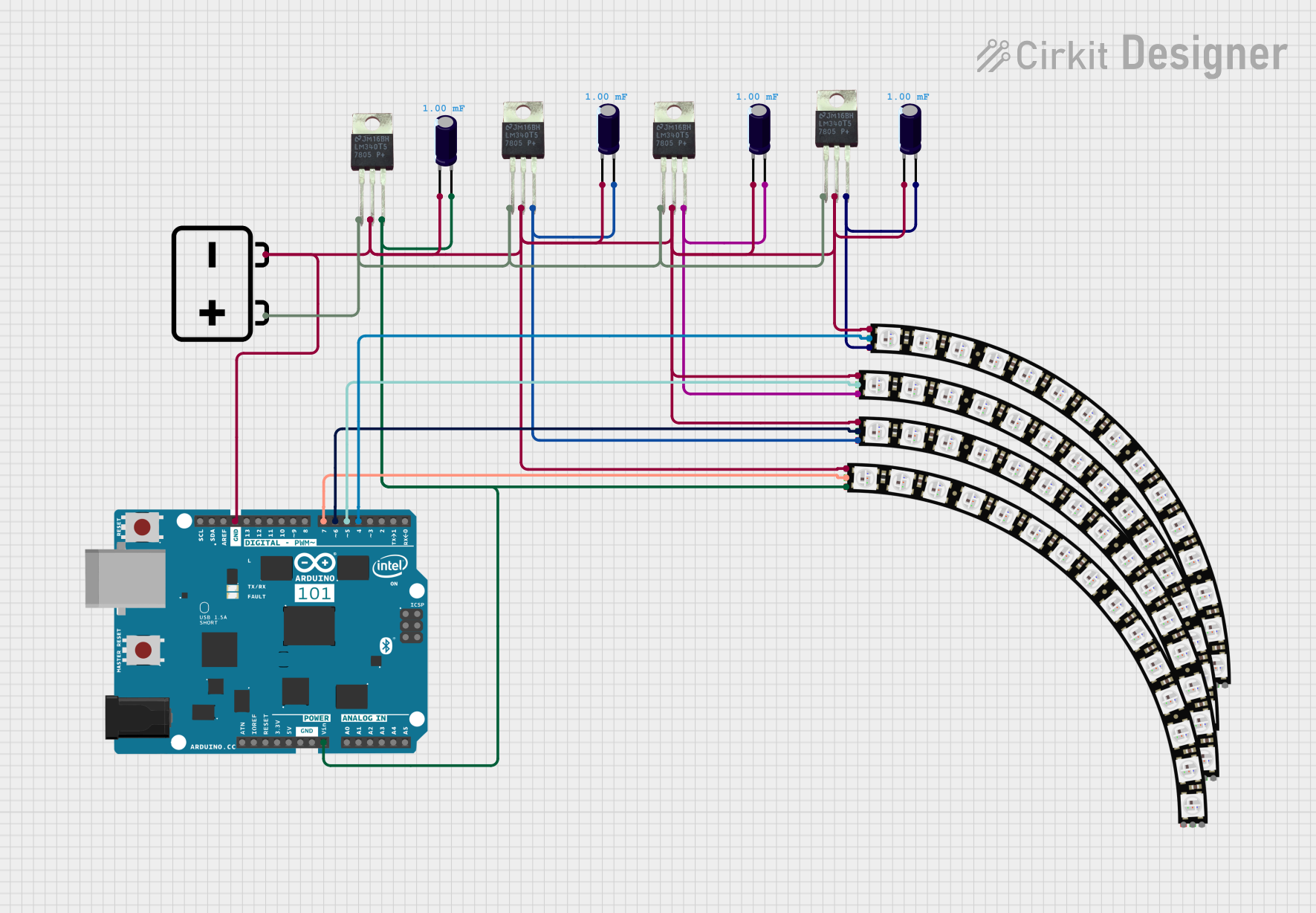
Circuit Documentation
Summary
This circuit is designed to control multiple Adafruit Quarter 60 NeoPixel Rings using an Arduino 101 microcontroller. The NeoPixel Rings are individually addressable LED rings that can be programmed to display a wide range of colors and patterns. The Arduino 101 is used to send data signals to the NeoPixel Rings to control the lighting sequences. The circuit also includes LM340T5 7805 voltage regulators to step down the voltage from a 12V battery to a stable 5V required by the NeoPixel Rings and the Arduino 101. Electrolytic capacitors are used across the power supply lines to smooth out any voltage spikes and provide a stable power supply to the components.
Component List
Microcontroller
- Arduino 101: A microcontroller board based on the Intel Curie, which is capable of Bluetooth Low Energy communications and sensor integration.
LED Rings
- Adafruit Quarter 60 NeoPixel Ring: Individually addressable RGB LED rings with 60 LEDs per ring, capable of producing a wide spectrum of colors.
Voltage Regulators
- LM340T5 7805: A series of fixed-voltage integrated-circuit voltage regulators designed to provide a stable 5V output from a higher voltage input.
Capacitors
- Electrolytic Capacitor: Used to filter the input and output of the voltage regulators, providing a stable voltage supply and reducing noise.
Power Supply
- 12v Battery: Provides the power source for the circuit.
Wiring Details
Arduino 101
- GND: Connected to the ground plane of the circuit.
- VIN: Connected to the positive terminal of the electrolytic capacitor to receive a stable 5V from the LM340T5 7805 voltage regulator.
- Digital Pins (D4, D5 PWM, D6 PWM, D7): Each connected to the DATAIN pin of a different Adafruit Quarter 60 NeoPixel Ring to control the LEDs.
Adafruit Quarter 60 NeoPixel Rings
- VDD: Connected to the Vout pin of an LM340T5 7805 voltage regulator.
- DATAIN: Connected to a digital pin on the Arduino 101 (D4, D5 PWM, D6 PWM, D7) to receive data signals.
- GND: Connected to the ground plane of the circuit.
- DATAOUT: Not connected in this circuit.
LM340T5 7805 Voltage Regulators
- Vin: Connected to the positive terminal of the 12V battery.
- Vout: Connected to the VDD pin of an Adafruit Quarter 60 NeoPixel Ring and the positive terminal of an electrolytic capacitor.
- GND: Connected to the ground plane of the circuit.
Electrolytic Capacitors
- + (Positive): Connected to the Vout pin of an LM340T5 7805 voltage regulator and the VDD pin of an Adafruit Quarter 60 NeoPixel Ring.
- - (Negative): Connected to the ground plane of the circuit.
12v Battery
- + (Positive): Connected to the Vin pin of all LM340T5 7805 voltage regulators.
- - (Negative): Connected to the ground plane of the circuit.
Documented Code
No code has been provided for the microcontroller. The code would typically include initialization of the NeoPixel library, setting up the data pins, and programming the desired lighting sequences for the NeoPixel Rings.
Please note that the actual implementation of the code is crucial for the operation of the circuit, and it should be written and uploaded to the Arduino 101 microcontroller to control the NeoPixel Rings. The code would handle the initialization of the NeoPixel library, define the pin connections, and include functions to control the color and brightness of the LEDs on the NeoPixel Rings.