
Solar-Powered USB Charger with Voltage Regulation and LED Indicator
View and Edit Project In Cirkit Designer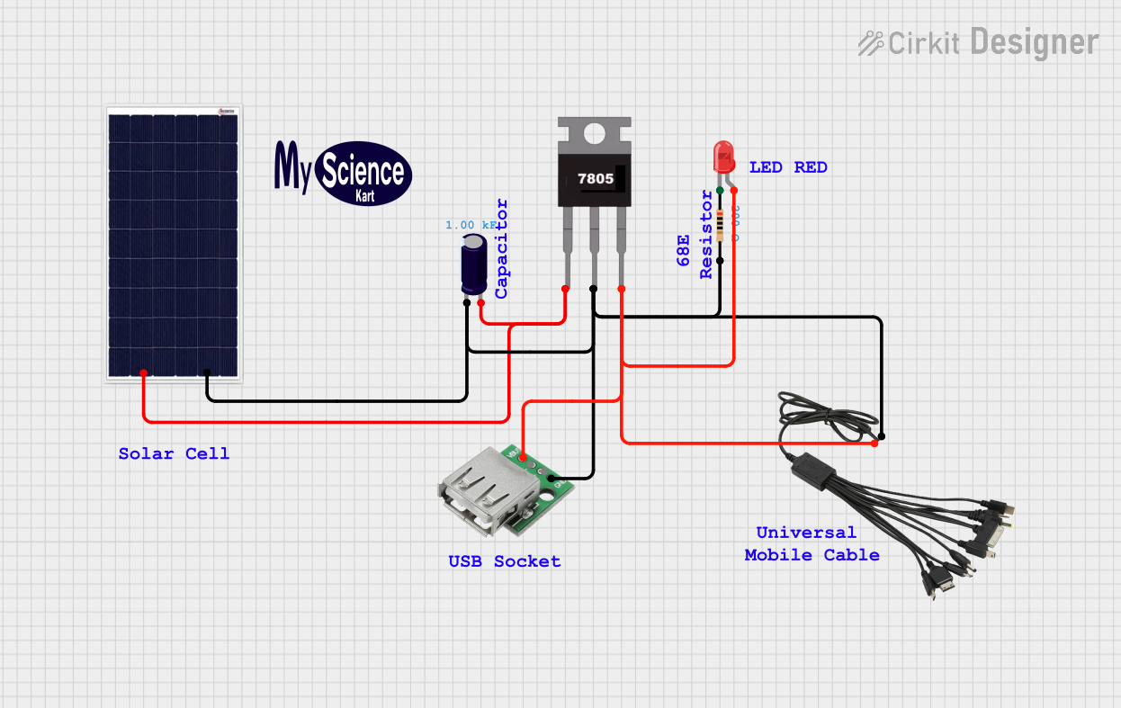
Circuit Documentation
Summary of the Circuit
This circuit appears to be a simple power supply and indicator system. It uses a solar cell to generate power, which is then regulated by a 7805 voltage regulator to provide a stable 5V output. This output is used to power a USB device and to light up an LED through a current-limiting resistor. An electrolytic capacitor is used to smooth out any voltage fluctuations from the solar cell.
Component List
Electrolytic Capacitor
- Description: A capacitor used for filtering and stabilizing the DC power supply.
- Capacitance: 1000 Farads
7805 Voltage Regulator
- Description: A voltage regulator that outputs a constant 5V DC.
- Pins: Vin, Gnd, Vout
LED: Two Pin (red)
- Description: A red light-emitting diode used as an indicator.
- Pins: cathode, anode
Resistor
- Description: A resistor used to limit the current through the LED.
- Resistance: 200 Ohms
USB Female Connector
- Description: A female USB connector used to provide power to a USB device.
- Pins: VCC, GND, -D, +D
Multi Charging Cable Universal
- Description: A cable used to distribute power from the circuit.
- Pins: + Positive, - Negative
Solar Cell
- Description: A photovoltaic cell used to convert solar energy into electrical power.
- Pins: Positive, Negative
Comments and Logo
- Description: Non-electrical components used for documentation or branding purposes.
Wiring Details
Electrolytic Capacitor
- Negative (-) pin connected to the ground net.
- Positive (+) pin connected to the input of the 7805 voltage regulator and the positive output of the solar cell.
7805 Voltage Regulator
- Vin connected to the positive output of the solar cell and the positive pin of the electrolytic capacitor.
- Gnd connected to the ground net.
- Vout connected to the VCC pin of the USB female connector, the positive pin of the multi charging cable, and the anode of the LED.
LED: Two Pin (red)
- Cathode connected to one pin of the resistor.
- Anode connected to the Vout of the 7805 voltage regulator.
Resistor
- One pin connected to the cathode of the LED.
- The other pin connected to the ground net.
USB Female Connector
- VCC pin connected to the Vout of the 7805 voltage regulator.
- GND pin connected to the ground net.
Multi Charging Cable Universal
-
- Positive pin connected to the Vout of the 7805 voltage regulator.
-
- Negative pin connected to the ground net.
Solar Cell
- Positive pin connected to the Vin of the 7805 voltage regulator and the positive pin of the electrolytic capacitor.
- Negative pin connected to the ground net.
Documented Code
There is no embedded code provided for any microcontrollers in this circuit. If in the future, a microcontroller is added to the circuit, the code will be documented in this section.