
Circuit Documentation
Summary of the Circuit
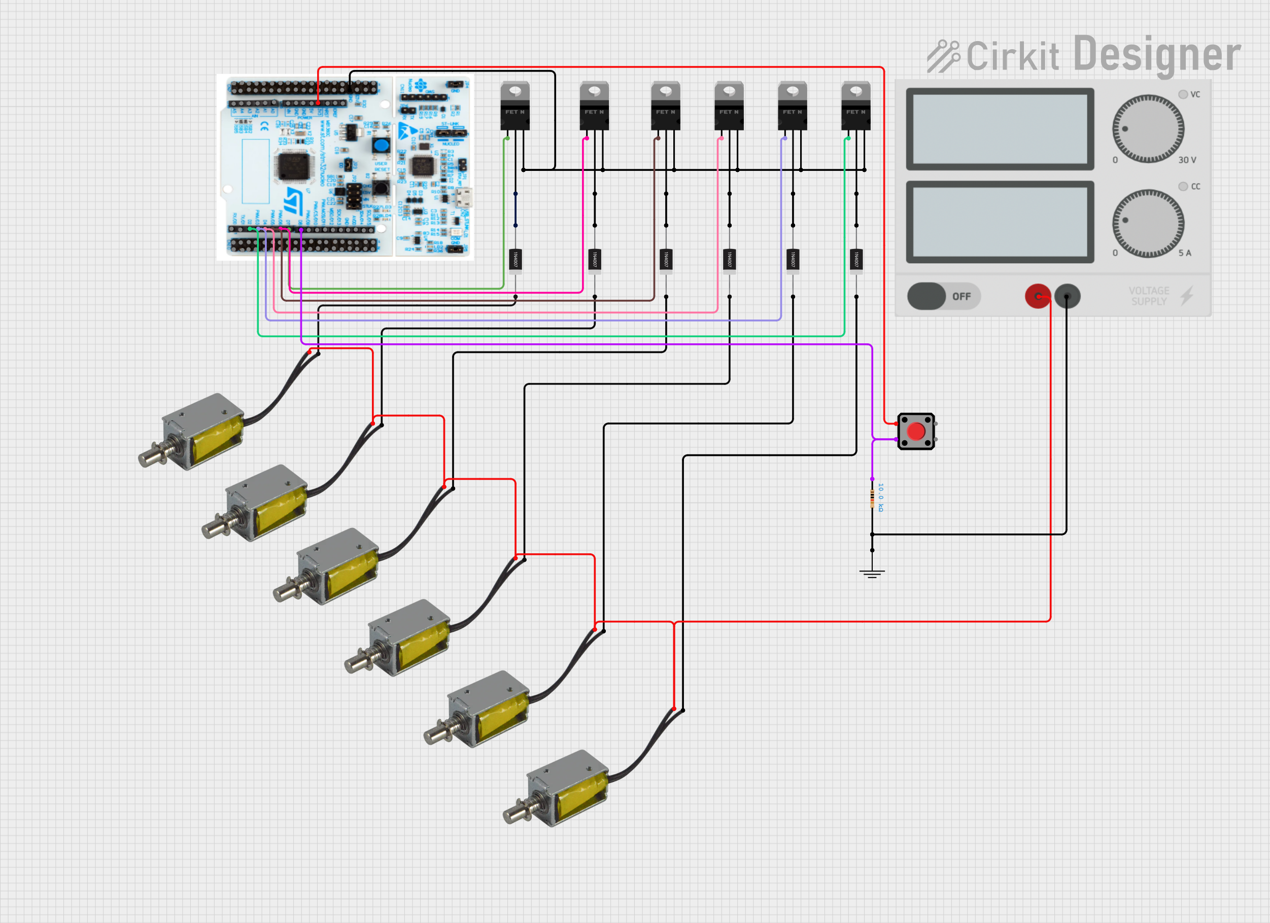
The circuit in question appears to be designed to control multiple push-pull solenoids using a microcontroller and a series of nMOS transistors. The microcontroller used is an STM32 Nucleo F303RE, which interfaces with the solenoids through the transistors. The solenoids are protected by 1N4007 rectifier diodes in a flyback diode configuration to prevent back EMF damage when the solenoids are turned off. A red pushbutton is included, likely for user input, and is debounced with a resistor. The power supply provides the necessary voltage to the solenoids and the microcontroller, with a common ground reference for the entire circuit.
Component List
Microcontroller
- STM32 Nucleo F303RE: A microcontroller board based on the STM32F303RE MCU, featuring a wide range of GPIO pins and capable of complex tasks.
Transistors
- nMOS Transistors (MOSFET): Used as switches to control the current flow to the solenoids from the microcontroller signals.
Diodes
- 1N4007 Rectifier Diodes: Used to protect the circuit from reverse current spikes when the solenoids are deactivated.
Solenoids
- Push Pull Solenoids: Actuators that convert electrical energy into linear motion when energized.
Power Supply
- Power Supply: Provides the required voltage and current to power the solenoids and the microcontroller.
Pushbutton
- Red Pushbutton: A user interface component that likely serves as an input to the microcontroller.
Resistor
- Resistor (10 kOhms): Used for debouncing the pushbutton signal.
Ground Reference
- GND: A common ground reference point for the circuit.
Wiring Details
STM32 Nucleo F303RE
- D8 connected to Red Pushbutton (Pin 1) through a 10 kOhm Resistor
- D7 connected to nMOS Transistor gate
- D6 connected to nMOS Transistor gate
- D5 connected to nMOS Transistor gate
- D4 connected to nMOS Transistor gate
- D3 connected to nMOS Transistor gate
- D2 connected to nMOS Transistor gate
- +3V3 connected to Red Pushbutton (Pin 4)
- GND connected to nMOS Transistor source (common for all MOSFETs)
nMOS Transistors (MOSFET)
- Gate connected to respective STM32 Nucleo F303RE pins (D2-D7)
- Source of all MOSFETs connected to GND
- Drain connected to Anode of respective 1N4007 Rectifier Diodes
1N4007 Rectifier Diodes
- Anode connected to Drain of respective nMOS Transistors
- Cathode connected to -ve of respective Push Pull Solenoids
Push Pull Solenoids
- +ve of all solenoids connected to + of Power Supply
- -ve connected to Cathode of respective 1N4007 Rectifier Diodes
Power Supply
-
- connected to +ve of all Push Pull Solenoids
-
- connected to GND
Red Pushbutton
- Pin 1 connected to D8 of STM32 Nucleo F303RE through a 10 kOhm Resistor
- Pin 4 connected to +3V3 of STM32 Nucleo F303RE
Resistor (10 kOhms)
- One end connected to Red Pushbutton (Pin 1)
- Other end connected to D8 of STM32 Nucleo F303RE and GND
GND
- Common ground reference for the circuit, connected to - of Power Supply and Source of all MOSFETs
Documented Code
No code was provided for the microcontroller. The expected code would likely initialize the GPIO pins connected to the MOSFET gates as outputs and include logic to control the solenoids based on the state of the pushbutton or other input conditions.