
ESP32-Based Location-Aware Distance Alert System with GPS and Ultrasonic Sensor
View and Edit Project In Cirkit Designer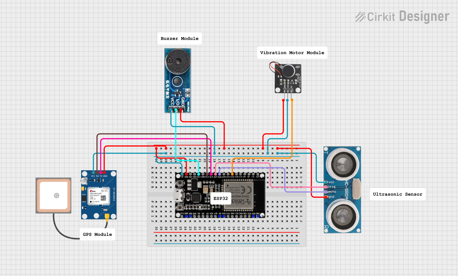
Circuit Documentation
Summary
The circuit in question is designed to interface an ESP32 microcontroller with a variety of sensors and modules, including an Ultrasonic Sensor, a PWM Vibration Motor Sensor Module, a Buzzer Module, and a GPS NEO 6M module. The ESP32 serves as the central processing unit, controlling the sensors and modules, and managing data communication between them. The circuit is powered by a 5V supply, which is distributed to all components. Ground connections are also unified across the circuit.
Component List
Buzzer Module
- Pins: GND, Vcc, I/O
- Description: A module that emits sound when provided with a signal.
Ultrasonic Sensor
- Pins: +VCC, Trigger, Echo, GND
- Description: A sensor that measures distance by emitting ultrasonic waves and timing their return.
PWM Vibration Motor Sensor Module Switch
- Pins: Signal, Vcc, Ground
- Description: A module that controls a vibration motor using PWM signals.
ESP32 38 PINS
- Pins: GND, G23, G22, TXD, RXD, G21, G19, G18, G5, G17, G16, G4, G0, G2, G15, SDI, SD0, CLK, 3V3, EN, SP, SN, G34, G35, G32, 33, G25, G26, G27, G14, G12, G13, SD2, SD3, 5V
- Description: A microcontroller with Wi-Fi and Bluetooth capabilities, featuring a wide range of GPIO pins for interfacing with various peripherals.
GPS NEO 6M
- Pins: VCC, RX, TX, GND
- Description: A GPS module capable of providing accurate location data.
Wiring Details
Buzzer Module
- GND: Connected to the common ground.
- Vcc: Connected to the 5V power supply.
- I/O: Connected to GPIO 13 (G13) on the ESP32.
Ultrasonic Sensor
- +VCC: Connected to the 5V power supply.
- Trigger: Connected to GPIO 27 (G27) on the ESP32.
- Echo: Connected to GPIO 26 (G26) on the ESP32.
- GND: Connected to the common ground.
PWM Vibration Motor Sensor Module Switch
- Signal: Connected to GPIO 32 (G32) on the ESP32.
- Vcc: Connected to the 5V power supply.
- Ground: Connected to the common ground.
ESP32 38 PINS
- GND: Connected to the common ground.
- 5V: Connected to the 5V power supply.
- G32: Connected to the Signal pin of the PWM Vibration Motor Sensor Module.
- G26: Connected to the Echo pin of the Ultrasonic Sensor.
- G27: Connected to the Trigger pin of the Ultrasonic Sensor.
- G14: Connected to the TX pin of the GPS NEO 6M.
- G12: Connected to the RX pin of the GPS NEO 6M.
- G13: Connected to the I/O pin of the Buzzer Module.
GPS NEO 6M
- VCC: Connected to the 5V power supply.
- RX: Connected to GPIO 12 (G12) on the ESP32.
- TX: Connected to GPIO 14 (G14) on the ESP32.
- GND: Connected to the common ground.
Documented Code
No code has been provided for the microcontroller. The documentation of the code would typically include a description of the functionality, setup, and main loop, along with comments explaining the purpose of each function and variable. Since no code is available, this section cannot be completed. If code becomes available, it should be documented here following the standard practices for code documentation, including descriptions of the purpose and functionality of each code block, functions, and variables.