
Circuit Documentation
Summary
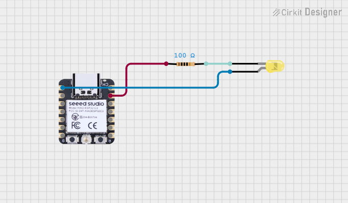
This circuit consists of an ESP32-C3 microcontroller, a resistor, and a yellow LED. The microcontroller is programmed to control the LED, turning it on and off at specified intervals while conserving power by entering deep sleep mode when not in use.
Component List
Resistor
- Component Name: Resistor
- Description: A resistor with a resistance of 100 Ohms.
- Pins: pin1, pin2
- Properties:
- Resistance: 100 Ohms
LED: Two Pin (yellow)
- Component Name: LED: Two Pin (yellow)
- Description: A yellow LED with two pins: anode and cathode.
- Pins: anode, cathode
XIAO ESP32C3
- Component Name: XIAO ESP32C3
- Description: An ESP32-C3 microcontroller with multiple GPIO pins.
- Pins: GPIO2/A0/D0, GPIO3/A1/D1, GPIO4/A2/D2, GPIO5/A3/D3, GPIO6/SDA/D4, GPIO7/SCL/D5, GPIO21/Tx/D6, 5V, GND, 3V3, GPIO10/MOSI/D10, GPIO9/MISO/D9, GPIO8/SCK/D8, GPIO20/Rx/D7
Wiring Details
Resistor
- pin1 is connected to GND of the XIAO ESP32C3.
- pin2 is connected to the cathode of the LED.
LED: Two Pin (yellow)
- anode is connected to GPIO2/A0/D0 of the XIAO ESP32C3.
- cathode is connected to pin2 of the resistor.
XIAO ESP32C3
- GND is connected to pin1 of the resistor.
- GPIO2/A0/D0 is connected to the anode of the LED.
Code Documentation
/*
 * This Arduino Sketch is for an ESP32-C3 microcontroller that drives one or
 * more LED lights. The microcontroller is powered by a 18650 Li-Ion battery,
 * which is charged by a solar panel through a CN3065 Solar Charge controller.
 * The microcontroller will use deep sleep mode during the day and when not in
 * use to conserve power.
 */

#define LED_PIN GPIO2 // Define the GPIO pin connected to the LED

void setup() {
  pinMode(LED_PIN, OUTPUT); // Set the LED pin as an output
  digitalWrite(LED_PIN, LOW); // Ensure the LED is off initially
  esp_sleep_enable_timer_wakeup(10 * 60 * 1000000); // Wake up every 10 minutes
  esp_deep_sleep_start(); // Enter deep sleep mode
}

void loop() {
  // This code will run after waking up from deep sleep
  digitalWrite(LED_PIN, HIGH); // Turn on the LED
  delay(1000); // Keep the LED on for 1 second
  digitalWrite(LED_PIN, LOW); // Turn off the LED
  esp_deep_sleep_start(); // Enter deep sleep mode again
}
This code sets up the ESP32-C3 microcontroller to control the LED. The LED is connected to GPIO2, which is defined as LED_PIN. The setup function initializes the LED pin as an output and ensures the LED is off initially. The microcontroller is set to wake up every 10 minutes and enter deep sleep mode to conserve power. The loop function runs after the microcontroller wakes up from deep sleep, turning the LED on for 1 second before turning it off and re-entering deep sleep mode.