
ESP8266 NodeMCU Controlled Relay and Touch Sensor Interface with RGB LED Feedback
View and Edit Project In Cirkit Designer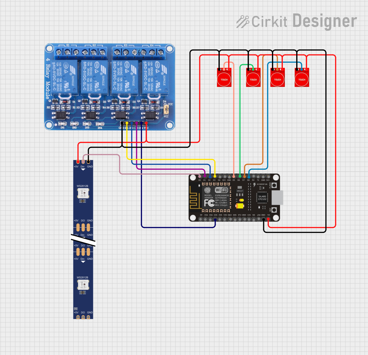
Circuit Documentation
Summary
This circuit integrates an ESP8266 NodeMCU microcontroller with a 4-channel 5V relay module, multiple TTP233 touch sensors, and a WS2812 RGB LED strip. The ESP8266 NodeMCU serves as the central processing unit, controlling the relay channels and reading touch sensor inputs to trigger specific actions, such as toggling the state of the relays or changing the color patterns of the LED strip. The relay module allows for controlling high-power devices, while the touch sensors provide a user interface for input. The LED strip offers visual feedback or ambient lighting.
Component List
ESP8266 NodeMCU
- Microcontroller with WiFi capability.
- Pins: D0, D1, D2, D3, D4, 3V3, GND, D5, D6, D7, D8, RX, TX, A0, RSV, SD3, SD2, SD1, CMD, SD0, CLK, EN, RST, VIN.
Relay 4 Channel 5V
- Module with 4 relays to control high power devices.
- Pins: GND, IN1, IN2, IN3, IN4, VCC, COM1, COM2, COM3, COM4, NO1, NO2, NO3, NO4, NC1, NC2, NC3, NC4.
Touch Sensor TTP233
- Capacitive touch sensor module.
- Pins: GND, I/O, VCC.
WS2812 RGB LED Strip
- Addressable LED strip for visual feedback and lighting.
- Pins: DIN, 5V, GND, DO.
Wiring Details
ESP8266 NodeMCU
- D0 connected to WS2812 RGB LED strip DIN.
- D1 connected to Relay 4 Channel 5V IN3.
- D2 connected to Relay 4 Channel 5V IN2.
- D3 connected to Relay 4 Channel 5V IN1.
- D5 connected to Touch Sensor TTP233 I/O.
- D6 connected to Touch Sensor TTP233 I/O.
- D7 connected to Touch Sensor TTP233 I/O.
- D8 connected to Touch Sensor TTP233 I/O.
- SD3 connected to Relay 4 Channel 5V IN4.
- GND connected to common ground.
- VIN connected to common VCC (5V).
Relay 4 Channel 5V
- GND connected to common ground.
- IN1, IN2, IN3, IN4 connected to ESP8266 NodeMCU D3, D2, D1, and SD3 respectively.
- VCC connected to common VCC (5V).
Touch Sensor TTP233 (Multiple Instances)
- GND connected to common ground.
- I/O connected to ESP8266 NodeMCU D5, D6, D7, and D8 respectively.
- VCC connected to common VCC (5V).
WS2812 RGB LED Strip
- DIN connected to ESP8266 NodeMCU D0.
- 5V connected to common VCC (5V).
- GND connected to common ground.
Documented Code
No code has been provided for the microcontroller. The documentation of the code would typically include details on the setup and loop functions, libraries used, and descriptions of custom functions and variables. Since no code is available, this section remains empty until the code is supplied.
Please note that the actual implementation of the circuit should ensure that the power requirements of all components are met and that the microcontroller pins are configured correctly for input or output as required. Additionally, proper safety measures should be taken when interfacing with high-power devices through the relay module.