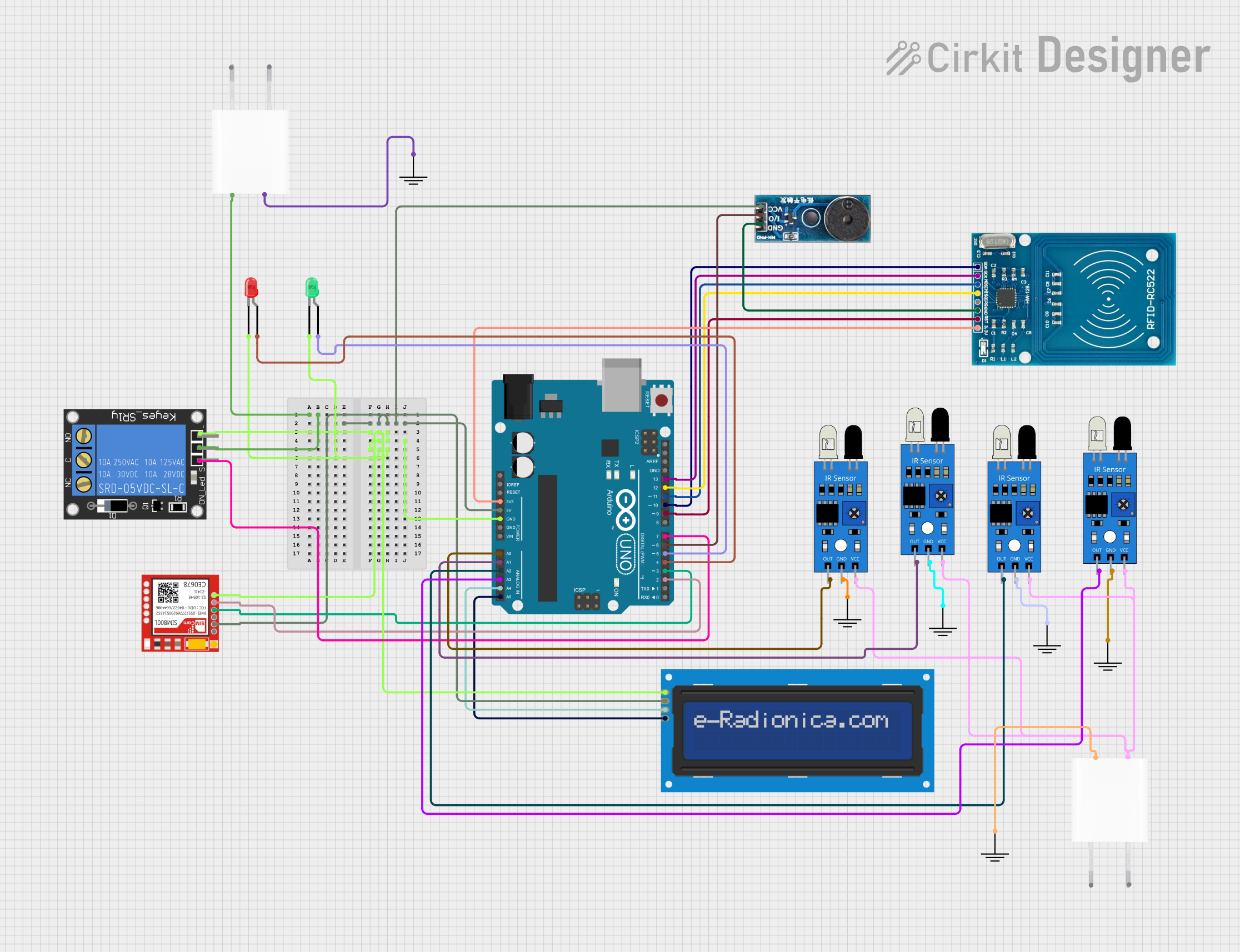
Arduino-Based RFID Car Parking System with IR Sensors and GSM Module

Circuit Documentation
Summary of the Circuit
The circuit is designed to control a car parking system. It utilizes an RFID scanner for identification, infrared sensors to detect available parking spaces, LEDs for visual status indication, a buzzer for auditory feedback, and an LCD display to show the parking status. The system is controlled by an Arduino UNO microcontroller, which manages the input from the sensors and the output to the display and indicators. The circuit also includes a relay for controlling an external load, possibly a barrier or gate, and a SIM800L module for GSM communication capabilities.
Component List
RFID-RC522
- Description: An RFID module for contactless communication using radio frequency.
- Pins: VCC (3.3V), RST, GND, IRQ, MISO, MOSI, SCK, SDA
LCD screen 16x2 I2C
- Description: A 16x2 character LCD display with an I2C interface for displaying information.
- Pins: SCL, SDA, VCC, GND
Buzzer Module
- Description: An electronic buzzer for producing audible signals.
- Pins: GND, Vcc, I/O
1-Channel Relay (5V 10A)
- Description: A relay module capable of switching high-power devices.
- Pins: NC, signal, C, power, NO, ground
Sim800l
- Description: A GSM/GPRS module for cellular communication.
- Pins: NET, RST, VCC, RXD, TXD, GND
Arduino UNO
- Description: A microcontroller board based on the ATmega328P.
- Pins: UNUSED, IOREF, Reset, 3.3V, 5V, GND, Vin, A0-A5, SCL, SDA, AREF, D0-D13
LED: Two Pin (red)
- Description: A red LED for visual indication.
- Pins: cathode, anode
LED: Two Pin (green)
- Description: A green LED for visual indication.
- Pins: cathode, anode
IR Sensor
- Description: An infrared sensor for detecting objects or movement.
- Pins: out, gnd, vcc
5V Adapter
- Description: A power adapter to provide a 5V supply.
- Pins: AC In 1, AC In 2, 5V, GND
GND
- Description: A ground reference point for the circuit.
- Pins: GND
Wiring Details
RFID-RC522
- VCC (3.3V) connected to Arduino UNO 3.3V
- RST connected to Arduino UNO D9
- GND connected to common ground
- MISO connected to Arduino UNO D12
- MOSI connected to Arduino UNO D11
- SCK connected to Arduino UNO D13
- SDA connected to Arduino UNO D10
LCD screen 16x2 I2C
- SCL connected to Arduino UNO A5
- SDA connected to Arduino UNO A4
- VCC connected to common 5V supply
- GND connected to common ground
Buzzer Module
- Vcc connected to common 5V supply
- GND connected to common ground
- I/O connected to Arduino UNO D6
1-Channel Relay (5V 10A)
- power connected to 5V supply from 5V Adapter
- ground connected to common ground
- signal connected to Arduino UNO D7
Sim800l
- VCC connected to common 5V supply
- GND connected to common ground
- RXD connected to Arduino UNO D3
- TXD connected to Arduino UNO D2
Arduino UNO
- 5V and GND pins connected to common power rails
- A0-A3 connected to IR sensors' out pins
- A4 (SDA) and A5 (SCL) connected to LCD I2C interface
- D2-D7 connected to various components as control signals
LEDs
- Red LED anode connected to Arduino UNO D4, cathode to common ground
- Green LED anode connected to Arduino UNO D5, cathode to common ground
IR Sensors
- out pins connected to Arduino UNO A0-A3
- vcc pins connected to common 5V supply
- gnd pins connected to common ground
5V Adapter
- 5V output connected to common 5V supply rail
- GND output connected to common ground rail
Documented Code
/*
 * Car Parking System
 * This Arduino sketch controls a car parking system using an RFID scanner,
 * infrared sensors, LEDs, a buzzer, and an LCD display. The system detects
 * available parking spaces and displays the status on the LCD. The buzzer
 * and LEDs provide visual and auditory feedback.
 */

#include <Wire.h>
#include <LiquidCrystal_I2C.h>
#include <SPI.h>
#include <MFRC522.h>

// Pin definitions
#define RFID_RST_PIN 9
#define RFID_SS_PIN 10
#define BUZZER_PIN 6
#define RED_LED_PIN 4
#define GREEN_LED_PIN 5
#define RELAY_PIN 7
#define IR_SENSOR_1_PIN A0
#define IR_SENSOR_2_PIN A1
#define IR_SENSOR_3_PIN A2
#define IR_SENSOR_4_PIN A3
#define SIM800L_RX_PIN 3
#define SIM800L_TX_PIN 2

// Create instances
LiquidCrystal_I2C lcd(0x27, 16, 2);
MFRC522 rfid(RFID_SS_PIN, RFID_RST_PIN);

void setup() {
  // Initialize serial communication
  Serial.begin(9600);
  // Initialize LCD
  lcd.begin();
  lcd.backlight();
  // Initialize RFID
  SPI.begin();
  rfid.PCD_Init();
  // Initialize pins
  pinMode(BUZZER_PIN, OUTPUT);
  pinMode(RED_LED_PIN, OUTPUT);
  pinMode(GREEN_LED_PIN, OUTPUT);
  pinMode(RELAY_PIN, OUTPUT);
  pinMode(IR_SENSOR_1_PIN, INPUT);
  pinMode(IR_SENSOR_2_PIN, INPUT);
  pinMode(IR_SENSOR_3_PIN, INPUT);
  pinMode(IR_SENSOR_4_PIN, INPUT);
  pinMode(SIM800L_RX_PIN, INPUT);
  pinMode(SIM800L_TX_PIN, OUTPUT);
  // Initial states
  digitalWrite(BUZZER_PIN, LOW);
  digitalWrite(RED_LED_PIN, LOW);
  digitalWrite(GREEN_LED_PIN, LOW);
  digitalWrite(RELAY_PIN, LOW);
  lcd.setCursor(0, 0);
  lcd.print("Car Parking System");
  delay(2000);
  lcd.clear();
}

void loop() {
  // Read IR sensors
  bool space1 = digitalRead(IR_SENSOR_1_PIN);
  bool space2 = digitalRead(IR_SENSOR_2_PIN);
  bool space3 = digitalRead(IR_SENSOR_3_PIN);
  bool space4 = digitalRead(IR_SENSOR_4_PIN);
  // Check parking spaces
  int availableSpaces = space1 + space2 + space3 + space4;
  // Update LCD
  lcd.setCursor(0, 0);
  lcd.print("Spaces: ");
  lcd.print(availableSpaces);
  // Update LEDs and buzzer
  if (availableSpaces > 0) {
    digitalWrite(GREEN_LED_PIN, HIGH);
    digitalWrite(RED_LED_PIN, LOW);
    digitalWrite(BUZZER_PIN, LOW);
  } else {
    digitalWrite(GREEN_LED_PIN, LOW);
    digitalWrite(RED_LED_PIN, HIGH);
    digitalWrite(BUZZER_PIN, HIGH);
  }
  delay(1000);
}
This code is responsible for the operation of the car parking system. It initializes the components, reads the status of the IR sensors to determine the number of available parking spaces, and updates the LCD display, LEDs, and buzzer accordingly.