Cirkit Designer
Your all-in-one circuit design IDE
Home /
Project Documentation
Arduino-Controlled Load Cell and DC Motor Interface with RTC Module
Circuit Documentation
Summary
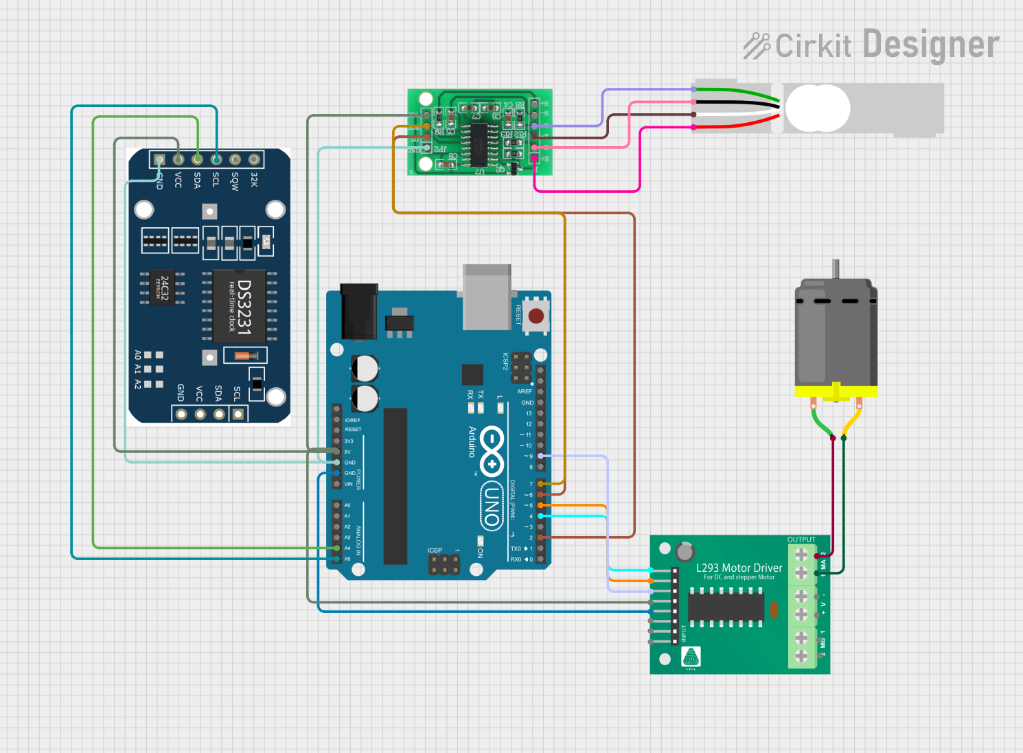
This circuit integrates various components to perform a set of functions that likely involve motor control, timekeeping, and weight measurement. An Arduino UNO serves as the central microcontroller, interfacing with an L293D motor driver to control a DC motor, an RTC (Real-Time Clock) module for timekeeping, and an HX711 bridge sensor interface connected to a load cell for weight measurement.
Component List
Arduino UNO
- Microcontroller board based on the ATmega328P
- It has 14 digital input/output pins, 6 analog inputs, a 16 MHz quartz crystal, a USB connection, a power jack, an ICSP header, and a reset button.
L293D Motor Driver
- A motor driver IC that allows DC motor to drive on either direction
- It has 4 input pins, 4 output pins, 2 enable pin, VCC and GND.
DC Motor
- An electric motor that runs on direct current (DC) electricity.
- It has 2 pins for power connection.
RTC Module
- A real-time clock module that keeps track of the current time.
- It typically includes a crystal oscillator and a battery to maintain timekeeping when the main power is off.
Load Cell - Red/white/black/green
- A transducer that is used to create an electrical signal whose magnitude is directly proportional to the force being measured.
- It has 4 pins for electrical connection.
HX711 - Bridge Sensor Interface
- A precision 24-bit analog-to-digital converter (ADC) designed for weigh scales and industrial control applications to interface directly with a bridge sensor.
Wiring Details
Arduino UNO
5Vconnected to VCC of HX711, L293D Motor Driver, and RTC ModuleGNDconnected to GND of HX711, L293D Motor Driver, and RTC ModuleA4 (SDA)connected to SDA of RTC ModuleA5 (SCL)connected to SCL of RTC ModuleD9connected to EN_A of L293D Motor DriverD7connected to SCK - CLOCK (IN) of HX711D6connected to DATA (OUT) of HX711D5connected to A2 of L293D Motor DriverD4connected to A1 of L293D Motor Driver
L293D Motor Driver
VCCconnected to 5V of Arduino UNOGNDconnected to GND of Arduino UNOEN_Aconnected to D9 of Arduino UNOA1connected to D4 of Arduino UNOA2connected to D5 of Arduino UNOMPIN_3connected to pin 2 of DC MotorMPIN_4connected to pin 1 of DC Motor
DC Motor
pin 1connected to MPIN_4 of L293D Motor Driverpin 2connected to MPIN_3 of L293D Motor Driver
RTC Module
VCCconnected to 5V of Arduino UNOGNDconnected to GND of Arduino UNOSDAconnected to A4 of Arduino UNOSCLconnected to A5 of Arduino UNO
Load Cell - Red/white/black/green
E+connected to E+ of HX711A-connected to A- of HX711E-connected to E- of HX711A+connected to A+ of HX711
HX711 - Bridge Sensor Interface
3.3/3.5V Supplyconnected to 5V of Arduino UNOGND - GROUNDconnected to GND of Arduino UNOSCK - CLOCK (IN)connected to D7 of Arduino UNODATA (OUT)connected to D6 of Arduino UNOE+connected to E+ of Load CellA-connected to A- of Load CellE-connected to E- of Load CellA+connected to A+ of Load Cell
Documented Code
Arduino UNO Code (sketch.ino)
void setup() {
  // put your setup code here, to run once:

}

void loop() {
  // put your main code here, to run repeatedly:

}
Note: The provided code is a template and does not include specific functionality. It needs to be filled in with the logic to control the motor driver, read data from the RTC module, and interface with the HX711 to read the load cell.