
74HC74 and 7408 Based LED Control Circuit with Push Switches
View and Edit Project In Cirkit Designer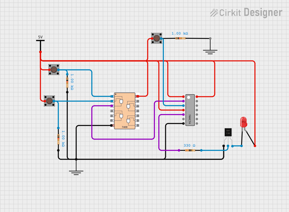
Circuit Documentation
Summary
This document provides a detailed description of a digital circuit that includes various components such as flip-flops, logic gates, LEDs, transistors, resistors, and push switches. The circuit is designed to perform specific logical operations and control an LED based on the input from push switches.
Component List
- 74HC74: Dual D-type flip-flop with set and reset.
- 7408: Quad 2-input AND gate.
- LED: Two Pin (red): Light Emitting Diode.
- BC547: NPN Bipolar Junction Transistor.
- GND: Ground connection.
- Vcc: Power supply connection.
- 2 Pin Push Switch: Momentary push button switch.
- Resistor (1000 Ohms): Resistor with 1000 Ohms resistance.
- Resistor (330 Ohms): Resistor with 330 Ohms resistance.
Wiring Details
74HC74
- Reset 1: Connected to Vcc, 2 Pin Push Switch (1), 2 Pin Push Switch (1), 2 Pin Push Switch (1), 7408 (Vcc), LED (anode), 74HC74 (Set 1), 74HC74 (VCC).
- Data 1: Connected to 7408 (3).
- Clock 1: Connected to 2 Pin Push Switch (2).
- Set 1: Connected to Vcc, 2 Pin Push Switch (1), 2 Pin Push Switch (1), 2 Pin Push Switch (1), 7408 (Vcc), LED (anode), 74HC74 (Reset 1), 74HC74 (VCC).
- Q1: Connected to Resistor (pin1).
- GND: Connected to GND, 7408 (Gnd), BC547 (collector), Resistor (pin2), Resistor (pin2).
- VCC: Connected to Vcc, 2 Pin Push Switch (1), 2 Pin Push Switch (1), 2 Pin Push Switch (1), 7408 (Vcc), LED (anode), 74HC74 (Reset 1), 74HC74 (Set 1).
7408
- 1: Connected to 2 Pin Push Switch (2), Resistor (pin1).
- 2: Connected to 2 Pin Push Switch (2), Resistor (pin1).
- 3: Connected to 74HC74 (Data 1).
- Gnd: Connected to GND, 7408 (Gnd), BC547 (collector), Resistor (pin2), Resistor (pin2).
- Vcc: Connected to Vcc, 2 Pin Push Switch (1), 2 Pin Push Switch (1), 2 Pin Push Switch (1), 7408 (Vcc), LED (anode), 74HC74 (Reset 1), 74HC74 (Set 1).
LED: Two Pin (red)
- cathode: Connected to BC547 (Emitter).
- anode: Connected to Vcc, 2 Pin Push Switch (1), 2 Pin Push Switch (1), 2 Pin Push Switch (1), 7408 (Vcc), 74HC74 (Reset 1), 74HC74 (Set 1), 74HC74 (VCC).
BC547
- collector: Connected to GND, 7408 (Gnd), Resistor (pin2), Resistor (pin2).
- base: Connected to Resistor (pin2).
- Emitter: Connected to LED (cathode).
GND
- GND: Connected to 7408 (Gnd), BC547 (collector), Resistor (pin2), Resistor (pin2), 74HC74 (GND).
Vcc
- Vcc: Connected to 2 Pin Push Switch (1), 2 Pin Push Switch (1), 2 Pin Push Switch (1), 7408 (Vcc), LED (anode), 74HC74 (Reset 1), 74HC74 (Set 1), 74HC74 (VCC).
2 Pin Push Switch
- 1: Connected to Vcc, 2 Pin Push Switch (1), 2 Pin Push Switch (1), 7408 (Vcc), LED (anode), 74HC74 (Reset 1), 74HC74 (Set 1), 74HC74 (VCC).
- 2: Connected to 7408 (1), Resistor (pin1).
Resistor (1000 Ohms)
- pin1: Connected to 2 Pin Push Switch (2), 7408 (2).
- pin2: Connected to GND, 7408 (Gnd), BC547 (collector).
Resistor (330 Ohms)
- pin1: Connected to 74HC74 (Q1).
- pin2: Connected to BC547 (base).
Documented Code
There is no microcontroller code provided for this circuit.
This documentation provides a comprehensive overview of the circuit, including the components used and their interconnections. The detailed wiring information ensures that the circuit can be accurately replicated or analyzed for further understanding.