
Arduino UNO Controlled Servo with 4x4 Keypad and LCD Interface
View and Edit Project In Cirkit Designer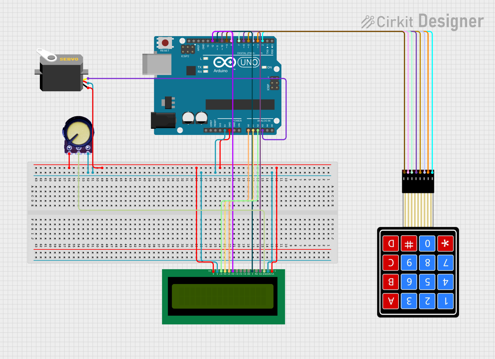
Circuit Documentation
Summary
This circuit integrates a 4x4 membrane matrix keypad, an Arduino UNO microcontroller, a servo motor, a potentiometer, and a 16x2 LCD display. The Arduino UNO serves as the central processing unit, interfacing with the keypad for user input, controlling the servo motor, and displaying information on the LCD. The potentiometer is used to adjust the contrast of the LCD display. The servo motor is controlled via one of the Arduino's PWM-capable digital pins. The keypad and LCD are connected to various digital pins on the Arduino for data input and output, respectively.
Component List
4X4 Membrane Matrix Keypad
- Description: A keypad with 16 buttons arranged in a 4x4 grid, used for user input.
- Pins: R1, R2, R3, R4, C1, C2, C3, C4
Arduino UNO
- Description: A microcontroller board based on the ATmega328P, used as the main controller for the circuit.
- Pins: UNUSED, IOREF, Reset, 3.3V, 5V, GND, Vin, A0, A1, A2, A3, A4, A5, SCL, SDA, AREF, D13, D12, D11, D10, D9, D8, D7, D6, D5, D4, D3, D2, D1, D0
Servo
- Description: An actuator that can be precisely controlled for position, used for mechanical movements.
- Pins: gnd, vcc, pulse
Potentiometer
- Description: A variable resistor, typically used to adjust levels such as volume or, in this case, LCD contrast.
- Pins: GND, Output, VCC
16X2 LCD
- Description: A liquid crystal display capable of displaying 16 characters in 2 rows, used for visual output.
- Pins: VSS, VDD, V0, RS, RW, E, D1, D0, D2, D3, D4, D6, D5, D7, A, K
Wiring Details
4X4 Membrane Matrix Keypad
- R1 connected to Arduino UNO D2
- R2 connected to Arduino UNO D3
- R3 connected to Arduino UNO D4
- R4 connected to Arduino UNO D5
- C1 connected to Arduino UNO D6
- C2 connected to Arduino UNO D7
- C3 connected to Arduino UNO D8
- C4 connected to Arduino UNO D9
Arduino UNO
- GND connected to 16X2 LCD VSS, 16X2 LCD K, Servo gnd, Potentiometer GND
- 5V connected to 16X2 LCD VDD, 16X2 LCD A, Servo vcc, Potentiometer VCC
- A0 connected to 16X2 LCD D5
- A1 connected to 16X2 LCD D6
- A2 connected to 16X2 LCD D7
- A3 connected to Servo pulse
- D12 connected to 16X2 LCD D4
- D11 connected to 16X2 LCD E
- D10 connected to 16X2 LCD RS
Servo
- gnd connected to Arduino UNO GND
- vcc connected to Arduino UNO 5V
- pulse connected to Arduino UNO A3
Potentiometer
- GND connected to Arduino UNO GND
- Output connected to 16X2 LCD V0
- VCC connected to Arduino UNO 5V
16X2 LCD
- VSS connected to Arduino UNO GND
- VDD connected to Arduino UNO 5V
- V0 connected to Potentiometer Output
- RS connected to Arduino UNO D10
- RW not connected (assumed to be tied to GND for write mode)
- E connected to Arduino UNO D11
- D4 connected to Arduino UNO D12
- D5 connected to Arduino UNO A0
- D6 connected to Arduino UNO A1
- D7 connected to Arduino UNO A2
- A connected to Arduino UNO 5V
- K connected to Arduino UNO GND
Documented Code
Arduino UNO Code (sketch.ino)
void setup() {
  // put your setup code here, to run once:

}

void loop() {
  // put your main code here, to run repeatedly:

}
Note: The provided code is a template and does not contain any functional code specific to the circuit's operation. It will need to be populated with the appropriate setup and loop code to control the keypad, servo, and LCD based on the circuit's requirements.