Arduino Nano-Based LED Timer with Push Button and Rocker Switch Control
Circuit Documentation
Summary
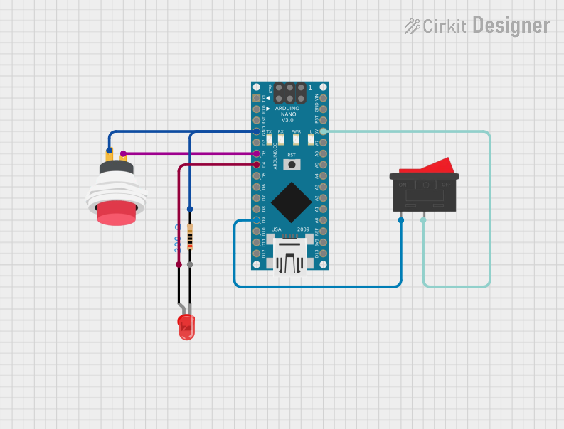
This circuit is designed to control an LED using a push button and a rocker switch. The Arduino Nano microcontroller is used to manage the input from the push button and rocker switch and control the LED accordingly. When the rocker switch is active, pressing the push button will turn on the LED for a specified interval (10 seconds). If the rocker switch is inactive, the LED remains off regardless of the push button state.
Component List
Arduino Nano
- Description: A small, complete, and breadboard-friendly microcontroller board based on the ATmega328P.
- Pins: D1/TX, D0/RX, RESET, GND, D2, D3, D4, D5, D6, D7, D8, D9, D10, D11/MOSI, D12/MISO, VIN, 5V, A7, A6, A5, A4, A3, A2, A1, A0, AREF, 3V3, D13/SCK
2Pin Push Switch
- Description: A simple push button switch with two pins.
- Pins: Input +, Output +
LED: Two Pin (red)
- Description: A red LED with two pins.
- Pins: cathode, anode
Resistor
- Description: A resistor with a resistance of 200 Ohms.
- Pins: pin1, pin2
- Properties: Resistance: 200 Ohms
Rocker Switch
- Description: A rocker switch with two pins.
- Pins: 1, 2
Wiring Details
Arduino Nano
- GND is connected to Output + of the 2Pin Push Switch and pin2 of the Resistor.
- D3 is connected to Input + of the 2Pin Push Switch.
- D4 is connected to anode of the LED: Two Pin (red).
- D9 is connected to pin 1 of the Rocker Switch.
- 5V is connected to pin 2 of the Rocker Switch.
2Pin Push Switch
- Output + is connected to GND of the Arduino Nano and pin2 of the Resistor.
- Input + is connected to D3 of the Arduino Nano.
LED: Two Pin (red)
- anode is connected to D4 of the Arduino Nano.
- cathode is connected to pin1 of the Resistor.
Resistor
- pin1 is connected to cathode of the LED: Two Pin (red).
- pin2 is connected to GND of the Arduino Nano and Output + of the 2Pin Push Switch.
Rocker Switch
- pin 1 is connected to D9 of the Arduino Nano.
- pin 2 is connected to 5V of the Arduino Nano.
Code Documentation
Arduino Nano Code
const int buttonPin = 3; // Pin connected to the push button
const int ledPin = 4;    // Pin connected to the LED
const int rockerPin = 9; // Pin connected to the rocker switch

unsigned long previousMillis = 0; // Stores the last time the LED was updated
const long interval = 10000;      // Interval for the LED to stay on (10 seconds)

bool ledState = LOW;              // Current state of the LED
bool circuitActive = false;       // State of the circuit (active/inactive)

void setup() {
  pinMode(buttonPin, INPUT_PULLUP); // Set button pin as input with internal pull-up resistor
  pinMode(ledPin, OUTPUT);          // Set LED pin as output
  pinMode(rockerPin, INPUT);        // Set rocker switch pin as input

  digitalWrite(ledPin, LOW);        // Ensure LED is off initially
}

void loop() {
  // Check the state of the rocker switch
  circuitActive = digitalRead(rockerPin);

  if (circuitActive) {
    // If the circuit is active, check the button state
    if (digitalRead(buttonPin) == LOW) {
      // If the button is pressed (active low), reset the timer and turn on the LED
      previousMillis = millis();
      ledState = HIGH;
      digitalWrite(ledPin, ledState);
    }

    // Check if the LED should be turned off
    if (ledState == HIGH && (millis() - previousMillis >= interval)) {
      ledState = LOW;
      digitalWrite(ledPin, ledState);
    }
  } else {
    // If the circuit is inactive, ensure the LED is off
    ledState = LOW;
    digitalWrite(ledPin, ledState);
  }
}
This code initializes the pins for the push button, LED, and rocker switch. It continuously checks the state of the rocker switch and push button. If the rocker switch is active and the push button is pressed, the LED is turned on for 10 seconds. If the rocker switch is inactive, the LED remains off.