
Circuit Documentation
Summary
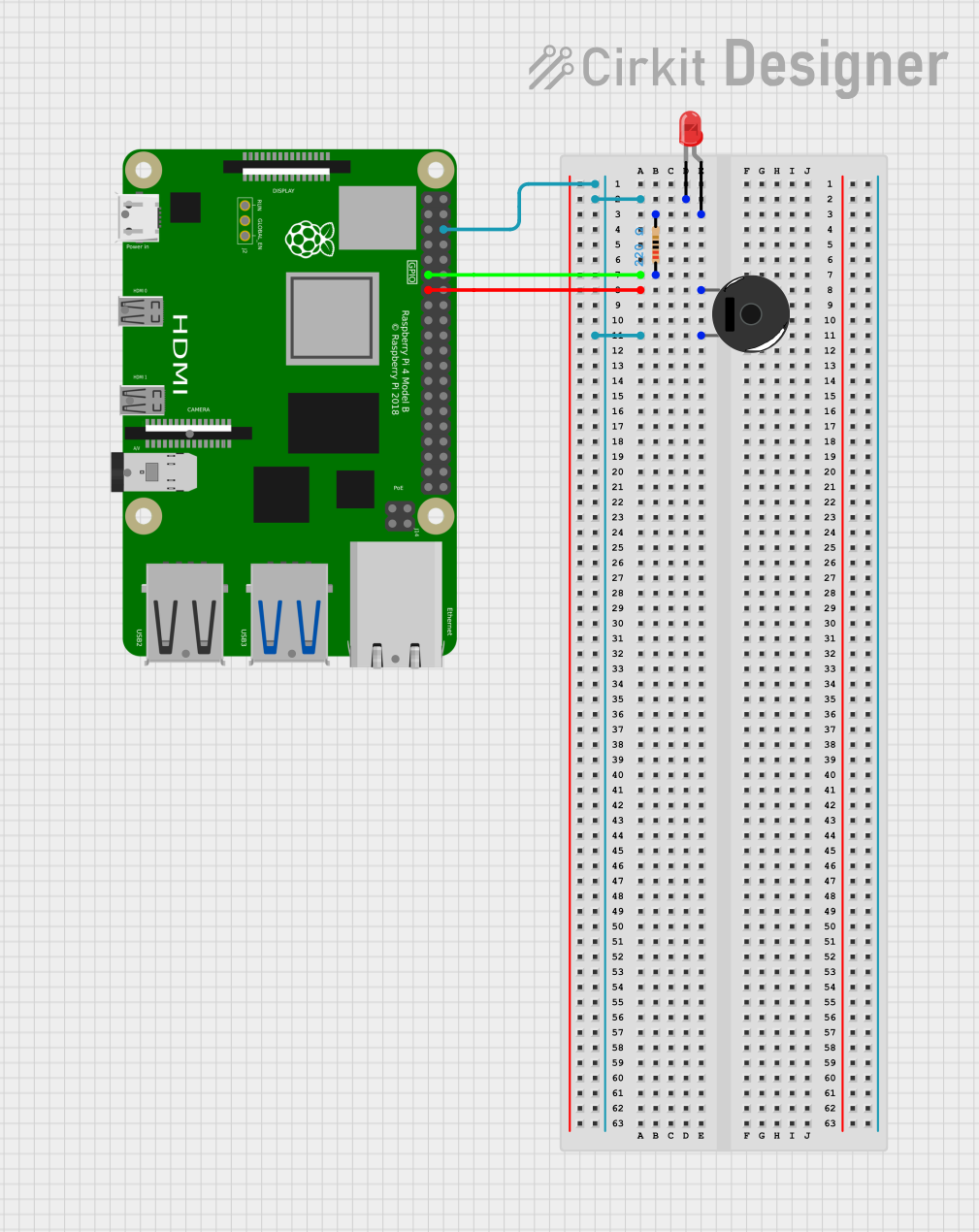
This circuit involves a Raspberry Pi 4B, a resistor, a red LED, and a piezo buzzer. The Raspberry Pi 4B serves as the central control unit, interfacing with the LED and the piezo buzzer through GPIO pins. The resistor is used to limit the current flowing through the LED.
Component List
Raspberry Pi 4B
- Description: A powerful single-board computer used for various applications including embedded systems and IoT projects.
- Pins:
- 3V3
- 5V
- GPIO2
- GPIO3
- GND
- GPIO4
- GPIO14
- GPIO15
- GPIO17
- GPIO18
- GPIO27
- GPIO22
- GPIO23
- GPIO24
- GPIO10
- GPIO9
- GPIO25
- GPIO11
- GPIO8
- GPIO7
- ID_SD
- GPIO5
- GPIO6
- GPIO12
- GPIO13
- GPIO19
- GPIO16
- GPIO26
- GPIO20
- GPIO21
- ID_SC
- TR01_TAP
- TR00_TAP
- TR03_TAP
- TR02_TAP
- RUN
- GLOBAL_EN
- ETH
- HDMI 0
- HDMI 1
- CAMERA
- AV
Resistor
- Description: A passive electrical component that limits the flow of electric current.
- Properties:
- Resistance: 220 Ohms
- Pins:
- pin1
- pin2
LED: Two Pin (red)
- Description: A light-emitting diode that emits red light when current flows through it.
- Pins:
- cathode
- anode
Piezo Buzzer
- Description: An electronic device that produces a sound when an electric signal is applied.
- Pins:
- pin 1
- pin 2
Wiring Details
Raspberry Pi 4B
GND is connected to:
- cathode of the LED
- pin 2 of the Piezo Buzzer
GPIO17 is connected to:
- pin1 of the Resistor
GPIO27 is connected to:
- pin 1 of the Piezo Buzzer
Resistor
pin1 is connected to:
- GPIO17 of the Raspberry Pi 4B
pin2 is connected to:
- anode of the LED
LED: Two Pin (red)
cathode is connected to:
- GND of the Raspberry Pi 4B
anode is connected to:
- pin2 of the Resistor
Piezo Buzzer
pin 1 is connected to:
- GPIO27 of the Raspberry Pi 4B
pin 2 is connected to:
- GND of the Raspberry Pi 4B
Code
No code is provided for this circuit.