Cirkit Designer
Your all-in-one circuit design IDE
Home /
Project Documentation
Battery-Powered Exhaust Fan with Rocker Switch Control
Circuit Documentation
Summary
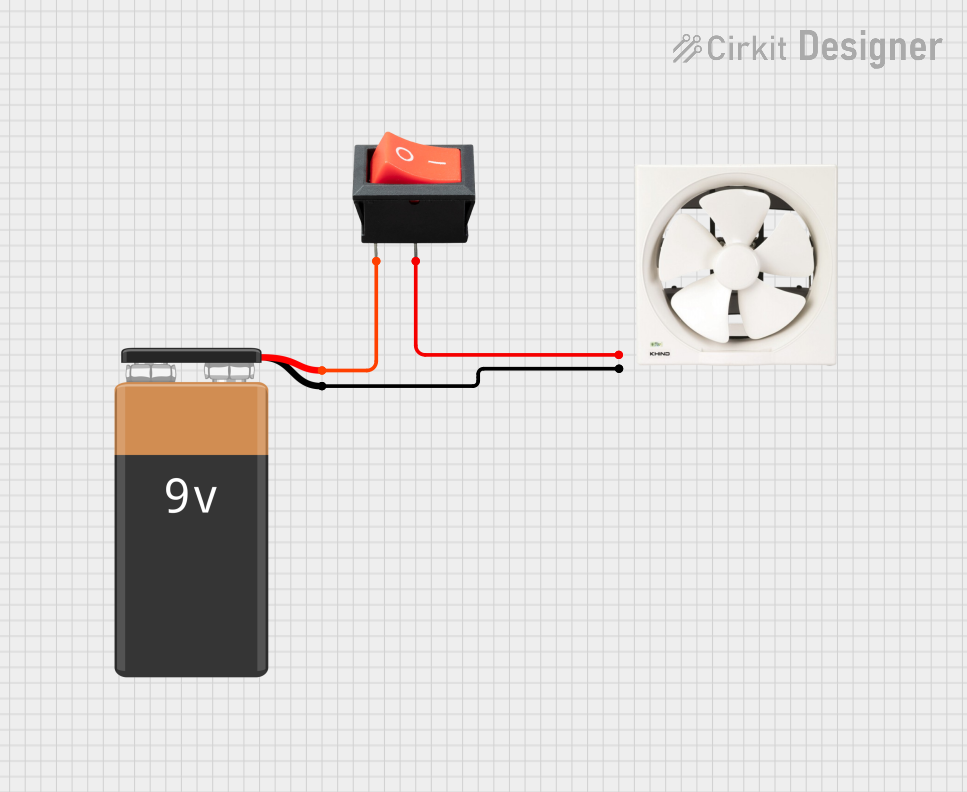
This document provides a detailed overview of a simple electrical circuit consisting of a 9V battery, a 12" exhaust fan, and a rocker switch. The circuit is designed to control the exhaust fan using the rocker switch, powered by the 9V battery.
Component List
9V Battery
- Description: A standard 9V battery used as the power source for the circuit.
- Pins:
+(Positive terminal)-(Negative terminal)
Exhaust Fan 12"
- Description: A 12-inch exhaust fan used for ventilation purposes.
- Pins:
Live(Live wire connection)Neutral(Neutral wire connection)
Rocker Switch
- Description: A rocker switch used to control the power to the exhaust fan.
- Pins:
input(Input terminal)output(Output terminal)
Wiring Details
9V Battery
- Pin
-is connected to the Neutral pin of the Exhaust Fan 12". - Pin
+is connected to the input pin of the Rocker Switch.
Exhaust Fan 12"
- Neutral pin is connected to the
-pin of the 9V Battery. - Live pin is connected to the output pin of the Rocker Switch.
Rocker Switch
- input pin is connected to the
+pin of the 9V Battery. - output pin is connected to the Live pin of the Exhaust Fan 12".
Documented Code
There is no microcontroller code associated with this circuit.