
Arduino UNO R4 WiFi Controlled Temperature and Humidity Display
View and Edit Project In Cirkit Designer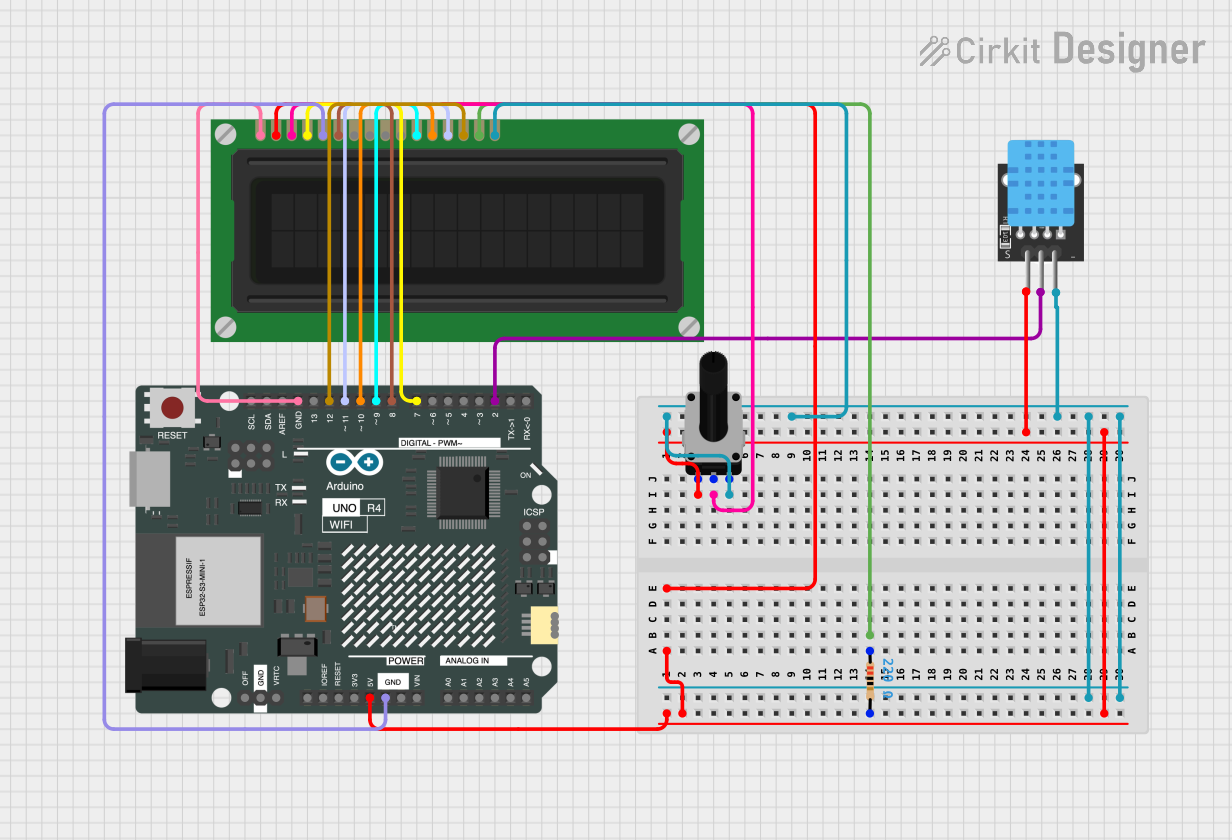
Circuit Documentation
Summary
The circuit in question is designed to interface an Arduino UNO R4 WiFi with an LCD display and a DHT11 temperature and humidity sensor. The LCD display is used to show the temperature and humidity readings obtained from the DHT11 sensor. A rotary potentiometer is included to adjust the contrast of the LCD display, and a resistor is used to provide the necessary current limiting for the backlight of the LCD.
Component List
Arduino UNO R4 WiFi
- Description: A microcontroller board based on the ATmega328P with WiFi capabilities.
- Pins: OFF, GND, VRTC, IIC0_SCL, IIC0_SDA, 3V3, GPIO 41, GPIO 0, GPIO 42, GPIO 43, GPIO 44, BOOT, IOREF, RESET, 5V, VIN, A0, A1, A2, A3, A4, A5, RSPCKA, CIPO, COPI, D0/RX, D1/TX, D2, D3, D4, D5, D6, D7, D8, D9, D10, D11, D12, D13, AREF, SDA, SCL
LCD Display (16 pin)
- Description: A 16x2 character LCD display module for displaying text and numbers.
- Pins: VSS, VDD, VO, RS, R_W, E, DB0, DB1, DB2, DB3, DB4, DB5, DB6, DB7, A, K
DHT11
- Description: A basic, ultra low-cost digital temperature and humidity sensor.
- Pins: 5V, S, GND
Rotary Potentiometer
- Description: A three-terminal resistor with a rotating contact that forms an adjustable voltage divider.
- Resistance: 10,000 Ohms
- Pins: leg1, wiper, leg2
Resistor
- Description: A passive two-terminal electrical component that implements electrical resistance as a circuit element.
- Resistance: 220 Ohms
- Pins: pin1, pin2
Wiring Details
Arduino UNO R4 WiFi
- 5V to LCD Display VDD, Rotary Potentiometer leg1, DHT11 5V
- GND to LCD Display VSS, R_W, DHT11 GND
- D2 to DHT11 S
- D7 to LCD Display RS
- D8 to LCD Display E
- D9 to LCD Display DB4
- D10 to LCD Display DB5
- D11 to LCD Display DB6
- D12 to LCD Display DB7
LCD Display (16 pin)
- VDD connected to 5V through a 220 Ohm resistor
- VO connected to Rotary Potentiometer wiper
- K connected to Rotary Potentiometer leg2
- RS, E, DB4, DB5, DB6, DB7 connected to Arduino UNO R4 WiFi digital pins D7, D8, D9, D10, D11, D12 respectively
- A connected to 5V through a 220 Ohm resistor
- R_W, VSS connected to GND
DHT11
- 5V to 5V power supply
- S to Arduino UNO R4 WiFi digital pin D2
- GND to ground
Rotary Potentiometer
- leg1 to 5V power supply
- wiper to LCD Display VO
- leg2 to LCD Display K and ground
Resistor
- pin1 to LCD Display A
- pin2 to 5V power supply (also connected to LCD Display VDD)
Documented Code
Arduino UNO R4 WiFi Code
#include <LiquidCrystal.h>
#include <DHT.h>

// Initialize the LCD library with the numbers of the interface pins
LiquidCrystal lcd(7, 8, 9, 10, 11, 12);

// Define DHT11 sensor pin and type
#define DHTPIN 2
#define DHTTYPE DHT11

DHT dht(DHTPIN, DHTTYPE);

void setup() {
  // Set up the LCD's number of columns and rows
  lcd.begin(16, 2);
  // Print a message to the LCD
  lcd.print("Temp & Humidity");

  // Initialize the DHT sensor
  dht.begin();
}

void loop() {
  // Wait a few seconds between measurements
  delay(2000);

  // Read temperature and humidity
  float h = dht.readHumidity();
  float t = dht.readTemperature();

  // Check if any reads failed and exit early (to try again)
  if (isnan(h) || isnan(t)) {
    lcd.setCursor(0, 1);
    lcd.print("Error reading");
    return;
  }

  // Print the temperature and humidity to the LCD
  lcd.setCursor(0, 1);
  lcd.print("T: ");
  lcd.print(t);
  lcd.print("C H: ");
  lcd.print(h);
  lcd.print("%");
}
This code is responsible for initializing the LCD and DHT11 sensor, reading temperature and humidity data from the DHT11 sensor, and displaying the readings on the LCD. If the sensor fails to provide valid readings, an error message is displayed on the LCD.