
Circuit Documentation
Summary of the Circuit
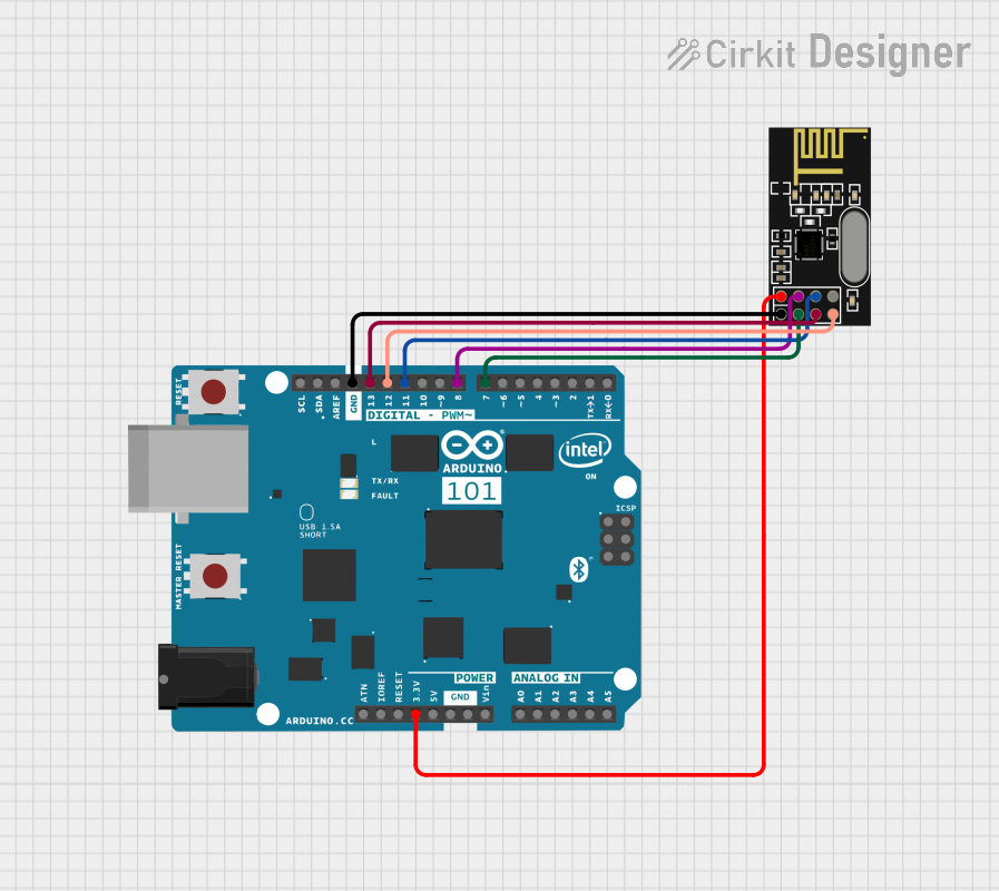
This circuit integrates an Arduino 101 microcontroller board with an NRF24L01 wireless transceiver module. The Arduino 101 provides the computational power and interfaces required for controlling the NRF24L01 module, which enables wireless communication capabilities. The connections between the Arduino 101 and the NRF24L01 include data lines for SPI communication, power supply lines, and control lines for chip enable and chip select functions.
Component List
Arduino 101
- Description: A microcontroller board based on the Intel Curie Module, designed for building IoT applications. It has a wide range of input/output pins including analog inputs, digital I/O, PWM outputs, and dedicated SPI pins.
- Pins: A5/SCL, A4/SDA, AREF, GND, D13/SCK, D12/MISO, D11 PWM/MOSI, D10 PWM/SS, D9 PWM, D8, D7, D6 PWM, D5 PWM, D4, D3 PWM, D2, D1/TX, D0/RX, AIN, ioref, RESET, 3V3, 5V, VIN, A0, A1, A2, A3, ICSP MISO, ICSP SCK, ICSP MOSI.
NRF24L01
- Description: A 2.4GHz wireless transceiver module that provides low power and high data rate options for wireless communication.
- Pins: IRQ (not used), MOSI, CSN, VCC (3V), GND, CE, SCK, MISO.
Wiring Details
Arduino 101
- GND connected to NRF24L01 GND
- D13/SCK connected to NRF24L01 SCK
- D12/MISO connected to NRF24L01 MISO
- D11 PWM/MOSI connected to NRF24L01 MOSI
- D8 connected to NRF24L01 CSN
- D7 connected to NRF24L01 CE
- 3V3 connected to NRF24L01 VCC (3V)
NRF24L01
- GND connected to Arduino 101 GND
- SCK connected to Arduino 101 D13/SCK
- MISO connected to Arduino 101 D12/MISO
- MOSI connected to Arduino 101 D11 PWM/MOSI
- CSN connected to Arduino 101 D8
- CE connected to Arduino 101 D7
- VCC (3V) connected to Arduino 101 3V3
Documented Code
No code has been provided for the microcontroller. Typically, the code would initialize the SPI interface, configure the NRF24L01 module, and implement the logic for sending and receiving data wirelessly. Without the code, we cannot document the specific functionalities implemented in this circuit.