
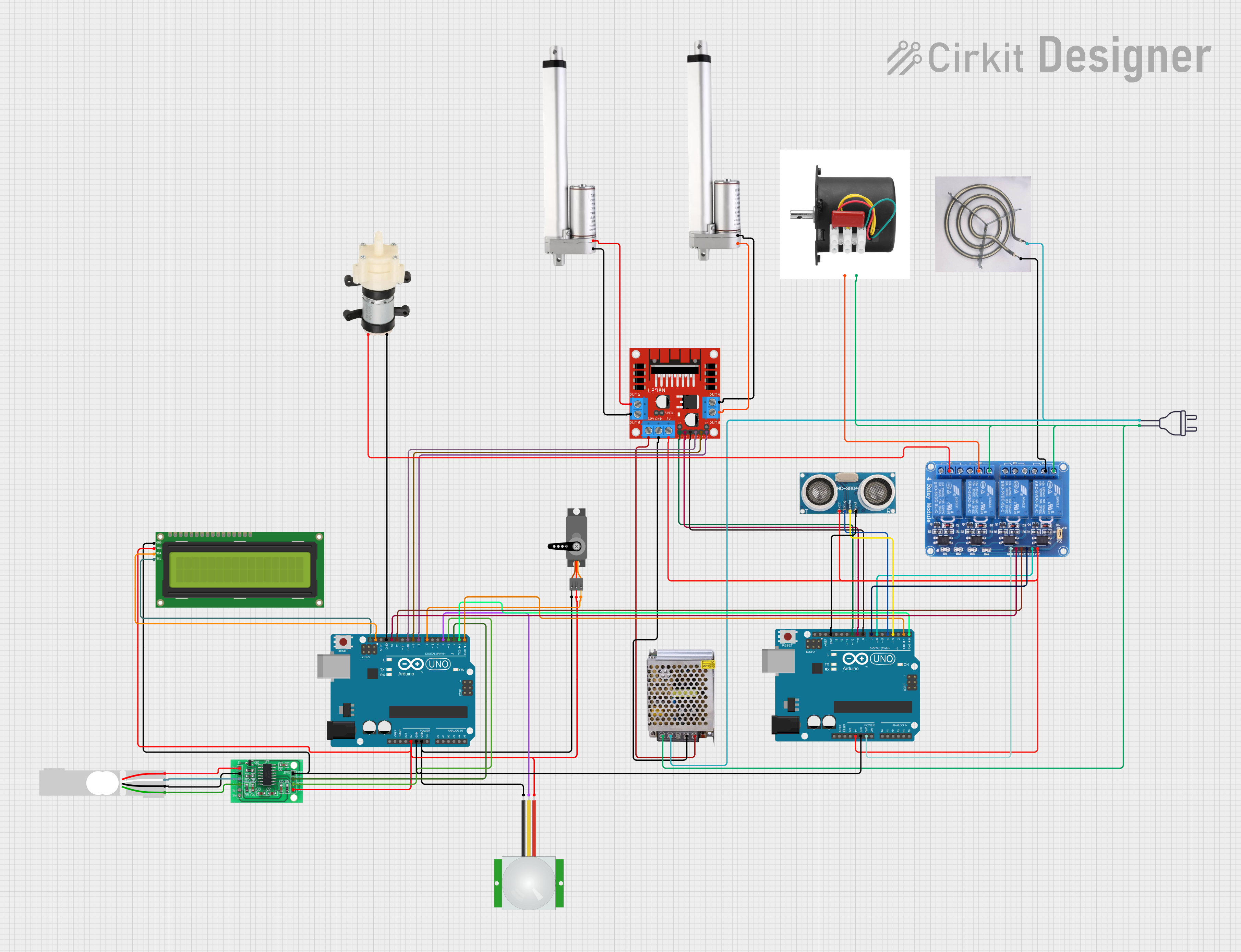
Circuit Documentation
Summary
The circuit in question is a complex system that integrates various components including microcontrollers, sensors, actuators, a motor driver, a relay module, power supplies, and an LCD screen. The primary control units are two Arduino UNO microcontrollers, which interface with the other components to perform a range of functions. The circuit is designed to handle both digital and analog signals, control actuators, and display information. Power distribution is carefully managed to ensure all components receive the correct voltages.
Component List
Microcontrollers
- Arduino UNO: A microcontroller board based on the ATmega328P. It has digital input/output pins, analog inputs, a USB connection for programming, and power jacks.
Sensors
- PIR sensor: Used to detect motion within its range.
- Ultrasonic Sensor: Measures distance by emitting ultrasonic waves and timing their return after bouncing off objects.
- HX711 - Bridge Sensor Interface: An ADC converter designed for weighing scales, interfacing with load cells.
- Load Cell - Red/white/black/green: A transducer that converts force into an electrical signal.
Actuators
- Relay 4 Channel 5v: An electrically operated switch that allows control of high-power devices with low-power signals.
- Actuator Motor: A motor that converts electrical energy into mechanical motion.
- Servo: A rotary actuator that allows for precise control of angular position.
- Mini Diaphragm Water Pump: A pump used for moving water or other fluids.
- AC 220v motor: An electric motor that operates on 220V AC power.
- Coil Heating: An electrical heating element.
Power Supplies
- POWER SUPPLY 12V 5AMP: Provides a 12V DC output from a 220V AC input.
- power 220v: Represents the main AC power supply.
Display
- I2C LCD 16x2 Screen: A liquid crystal display capable of showing 16 characters per line on 2 lines.
Motor Driver
- L298N DC motor driver: A dual H-bridge motor driver that allows for the control of two DC motors or one stepper motor.
Wiring Details
Arduino UNO
- 5V: Powers the relay module, ultrasonic sensor, motor driver, and other 5V components.
- GND: Common ground for the circuit.
- Digital Pins (D2-D13): Control signals for the motor driver, relay module, and sensors.
- Analog Pins (A0-A5): Unused in this circuit.
- I2C (SCL, SDA): Communication with the I2C LCD screen.
Relay 4 Channel 5v
- VCC: Connected to 5V power.
- GND: Connected to ground.
- IN1-IN4: Control inputs from the Arduino UNO digital pins.
- COM1-COM4: Common poles for relay switches.
- NO1-NO4, NC1-NC4: Normally open and normally closed contacts for connecting external devices.
L298N DC motor driver
- 5V: Powers the internal logic.
- 12V: Motor power supply from the 12V power supply.
- GND: Connected to ground.
- ENA, ENB: Enable pins for motor channels, controlled by Arduino UNO.
- IN1-IN4: Input pins for motor direction control, connected to Arduino UNO.
- OUT1-OUT4: Outputs to the actuator motors.
POWER SUPPLY 12V 5AMP
- 220V Positive Pole (AC): Connected to the main AC power supply.
- 220V Negative Pole (AC): Connected to the main AC power supply.
- GND (DC): Ground for the DC circuit.
- 12V-24V Output (DC): Provides power to the motor driver and other 12V components.
PIR sensor
- VDD: Connected to 5V power.
- SIG: Signal output to the Arduino UNO.
- GND: Connected to ground.
I2C LCD 16x2 Screen
- SCL: I2C clock line connected to Arduino UNO.
- SDA: I2C data line connected to Arduino UNO.
- VCC (5V): Power supply.
- GND: Connected to ground.
Actuator Motor
- 12 V: Connected to the motor driver output.
- Ground: Connected to the motor driver output.
Servo
- VCC: Connected to 5V power.
- GND: Connected to ground.
- PWM: Pulse Width Modulation control signal from Arduino UNO.
Mini Diaphragm Water Pump
- Positive (+): Connected to the relay module.
- Negative (-): Connected to ground.
HX711 - Bridge Sensor Interface
- E+, E-: Excitation voltage for the load cell.
- A-, A+: Load cell signal inputs.
- GND - GROUND: Connected to ground.
- DATA (OUT): Data output to Arduino UNO.
- SCK - CLOCK (IN): Clock input from Arduino UNO.
- 3.3/3.5V Supply: Power supply.
Load Cell - Red/white/black/green
- E+, E-: Excitation voltage connections.
- A-, A+: Signal outputs to the HX711 interface.
Documented Code
Arduino UNO (Primary Controller)
void setup() {
  // put your setup code here, to run once:

}

void loop() {
  // put your main code here, to run repeatedly:

}
Arduino UNO (Secondary Controller)
void setup() {
  // put your setup code here, to run once:

}

void loop() {
  // put your main code here, to run repeatedly:

}
Note: The provided code snippets are placeholders and need to be populated with the actual logic to control the circuit components as per the requirements.