Cirkit Designer
Your all-in-one circuit design IDE
Home /
Project Documentation
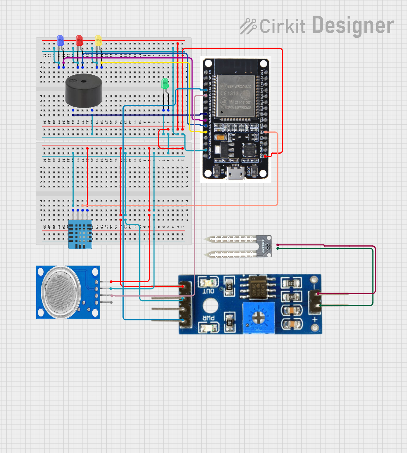
ESP32-Based Smart Environmental Monitoring System with Multi-Color LED Indicators
Circuit Documentation
Summary
This document provides a detailed overview of a circuit that includes an ESP32 microcontroller, various LEDs, a buzzer, a DHT11 humidity and temperature sensor, a soil moisture module, a water sensor, and an MQ135 gas sensor. The circuit is designed to interface these components with the ESP32 for various sensing and output functionalities.
Component List
ESP32
- Description: A powerful microcontroller with Wi-Fi and Bluetooth capabilities.
- Pins: EN, VP, VN, D34, D35, D32, D33, D25, D26, D27, D14, D12, D13, GND, VIN, 3V3, D15, D2, D4, RX2, TX2, D5, D18, D19, D21, RX0, TX0, D22, D23, BOOT
LED: Two Pin (green)
- Description: A green LED with two pins.
- Pins: cathode, anode
LED: Two Pin (red)
- Description: A red LED with two pins.
- Pins: cathode, anode
LED: Two Pin (blue)
- Description: A blue LED with two pins.
- Pins: cathode, anode
LED: Two Pin (yellow)
- Description: A yellow LED with two pins.
- Pins: cathode, anode
Buzzer
- Description: A simple buzzer for sound output.
- Pins: PIN, GND
DHT11 Humidity and Temperature Sensor
- Description: A sensor for measuring humidity and temperature.
- Pins: VDD, DATA, NULL, GND
Soil Moisture Module
- Description: A module for measuring soil moisture levels.
- Pins: positive, negative, Analog, Digital, Ground, VCC
Water Sensor
- Description: A sensor for detecting water presence.
- Pins: -, +
MQ135
- Description: A gas sensor for detecting air quality.
- Pins: VCC, GND, A0, D0
Wiring Details
ESP32
- GND: Connected to the cathode of the green LED, yellow LED, red LED, blue LED, GND of the buzzer, GND of the MQ135, Ground of the Soil Moisture Module, and GND of the DHT11 sensor.
- 3V3: Connected to VCC of the MQ135, VCC of the Soil Moisture Module, and VDD of the DHT11 sensor.
- D14: Connected to the anode of the yellow LED.
- D27: Connected to the anode of the red LED.
- D25: Connected to the PIN of the buzzer.
- D26: Connected to the anode of the blue LED.
- D4: Connected to the DATA pin of the DHT11 sensor.
- D34: Connected to the Analog pin of the Soil Moisture Module.
- D35: Connected to the A0 pin of the MQ135.
LED: Two Pin (green)
- cathode: Connected to GND.
- anode: Not connected.
LED: Two Pin (red)
- cathode: Connected to GND.
- anode: Connected to D27 of the ESP32.
LED: Two Pin (blue)
- cathode: Connected to GND.
- anode: Connected to D26 of the ESP32.
LED: Two Pin (yellow)
- cathode: Connected to GND.
- anode: Connected to D14 of the ESP32.
Buzzer
- GND: Connected to GND.
- PIN: Connected to D25 of the ESP32.
DHT11 Humidity and Temperature Sensor
- VDD: Connected to 3V3 of the ESP32.
- DATA: Connected to D4 of the ESP32.
- GND: Connected to GND.
Soil Moisture Module
- positive: Connected to the "-" pin of the Water Sensor.
- negative: Connected to the "+" pin of the Water Sensor.
- Analog: Connected to D34 of the ESP32.
- Ground: Connected to GND.
- VCC: Connected to 3V3 of the ESP32.
Water Sensor
- -: Connected to the positive pin of the Soil Moisture Module.
- +: Connected to the negative pin of the Soil Moisture Module.
MQ135
- VCC: Connected to 3V3 of the ESP32.
- GND: Connected to GND.
- A0: Connected to D35 of the ESP32.
Documented Code
ESP32 Code
void setup() {
  // put your setup code here, to run once:

}

void loop() {
  // put your main code here, to run repeatedly:

}
Buzzer Code
void setup() {
  // put your setup code here, to run once:

}

void loop() {
  // put your main code here, to run repeatedly:

}
This document provides a comprehensive overview of the circuit, including the components used, their wiring details, and the code for the microcontrollers.