
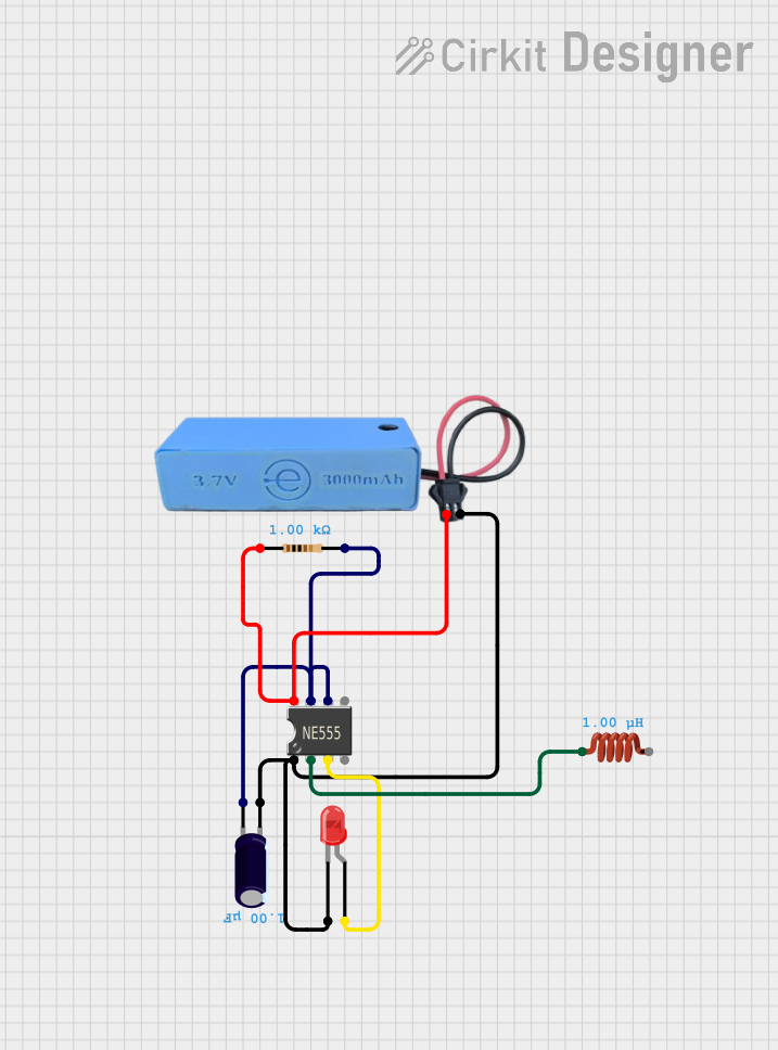
Circuit Documentation
Summary
This document provides a detailed description of a circuit that includes a 555 Timer IC, a battery, a resistor, an electrolytic capacitor, an LED, and an inductor. The circuit is designed to utilize the 555 Timer IC in an astable mode to blink an LED. The power is supplied by a 3.7V battery, and the circuit includes passive components such as a resistor, capacitor, and inductor to control the timing and behavior of the 555 Timer IC.
Component List
Battery ERA
- Description: Provides 3.7V power supply.
- Pins: 3.7v, GND
555 Timer IC
- Description: A versatile timer IC used for generating precise time delays or oscillation.
- Pins: VCC+, Dis, Th, CV, Rst, Out, Trig, GND
Resistor
- Description: Limits the current flow in the circuit.
- Pins: pin1, pin2
- Properties:
- Resistance: 1000 Ohms
Electrolytic Capacitor
- Description: Stores electrical energy temporarily.
- Pins: -, +
- Properties:
- Capacitance: 0.000001 Farads
LED: Two Pin (red)
- Description: Emits light when current flows through it.
- Pins: cathode, anode
Inductor
- Description: Stores energy in a magnetic field when electrical current flows through it.
- Pins: pin 0, pin 1
- Properties:
- Inductance: 0.000001 Henrys
Wiring Details
Battery ERA
3.7v is connected to:
- VCC+ of 555 Timer IC
- pin1 of Resistor
GND is connected to:
- GND of 555 Timer IC
-
- of Electrolytic Capacitor
- cathode of LED: Two Pin (red)
555 Timer IC
VCC+ is connected to:
- 3.7v of Battery ERA
- pin1 of Resistor
GND is connected to:
- GND of Battery ERA
-
- of Electrolytic Capacitor
- cathode of LED: Two Pin (red)
Dis is connected to:
- Th of 555 Timer IC
-
- of Electrolytic Capacitor
- pin2 of Resistor
Th is connected to:
- Dis of 555 Timer IC
-
- of Electrolytic Capacitor
- pin2 of Resistor
Out is connected to:
- anode of LED: Two Pin (red)
Trig is connected to:
- pin 0 of Inductor
Resistor
pin1 is connected to:
- VCC+ of 555 Timer IC
- 3.7v of Battery ERA
pin2 is connected to:
- Dis of 555 Timer IC
- Th of 555 Timer IC
-
- of Electrolytic Capacitor
Electrolytic Capacitor
- is connected to:
- GND of 555 Timer IC
- GND of Battery ERA
- cathode of LED: Two Pin (red)
+ is connected to:
- Dis of 555 Timer IC
- Th of 555 Timer IC
- pin2 of Resistor
LED: Two Pin (red)
cathode is connected to:
- GND of 555 Timer IC
- GND of Battery ERA
-
- of Electrolytic Capacitor
anode is connected to:
- Out of 555 Timer IC
Inductor
pin 0 is connected to:
- Trig of 555 Timer IC
pin 1 is not connected to any other component in this circuit.
Code
There is no microcontroller code provided for this circuit.
This document provides a comprehensive overview of the circuit, including a summary, detailed component list, wiring details, and code documentation.