
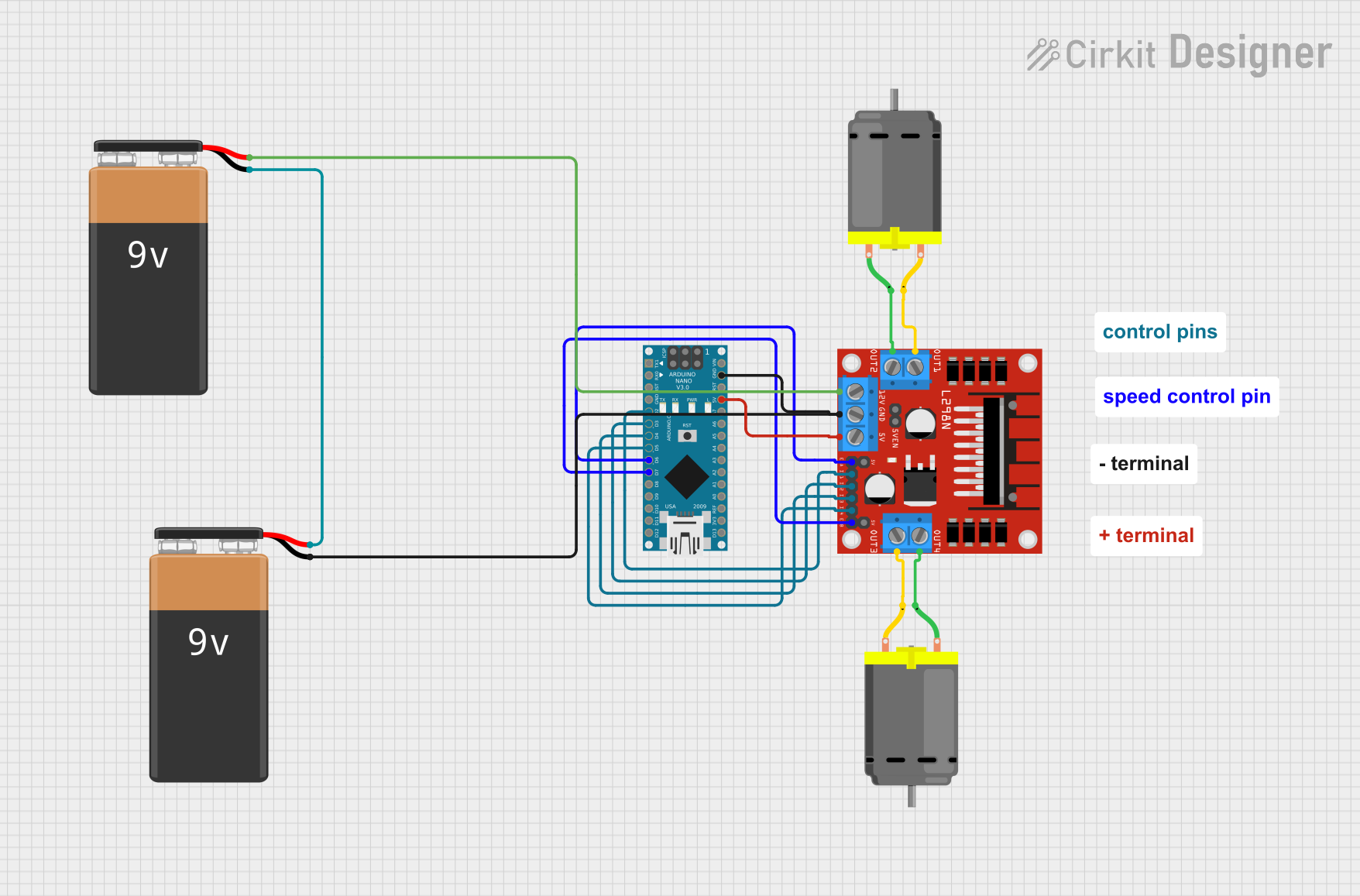
Circuit Documentation
Summary
This circuit is designed to control two DC motors using an Arduino Nano microcontroller and an L298N DC motor driver. The Arduino Nano is responsible for generating control signals that are sent to the L298N driver, which in turn drives the motors. The motors can be moved forward or backward, and their speed can be controlled. The circuit is powered by two 9V batteries, one for the Arduino Nano and the other for the L298N motor driver.
Component List
Arduino Nano
- Microcontroller board based on the ATmega328P
- Pins: D1/TX, D0/RX, RESET, GND, D2, D3, D4, D5, D6, D7, D8, D9, D10, D11/MOSI, D12/MISO, VIN, 5V, A7, A6, A5, A4, A3, A2, A1, A0, AREF, 3V3, D13/SCK
L298N DC Motor Driver
- Dual H-bridge motor driver for controlling two DC motors
- Pins: OUT1, OUT2, 12V, GND, 5V, OUT3, OUT4, 5V-ENA-JMP-I, 5V-ENA-JMP-O, +5V-J1, +5V-J2, ENA, IN1, IN2, IN3, IN4, ENB
DC Motor (x2)
- Standard DC motor for motion applications
- Pins: pin 1, pin 2
9V Battery (x2)
- Standard 9V battery for power supply
- Pins: -, +
Wiring Details
Arduino Nano
- D2 connected to L298N IN1
- D3 connected to L298N IN2
- D4 connected to L298N IN3
- D5 connected to L298N IN4
- D6 connected to L298N ENA
- D7 connected to L298N ENB
- GND connected to 9V Battery (-) and L298N GND
- 5V connected to L298N 5V
L298N DC Motor Driver
- OUT1 connected to DC Motor (Motor 1) pin 2
- OUT2 connected to DC Motor (Motor 1) pin 1
- OUT3 connected to DC Motor (Motor 2) pin 2
- OUT4 connected to DC Motor (Motor 2) pin 1
- 12V connected to 9V Battery (+)
- GND connected to Arduino Nano GND and 9V Battery (-)
- 5V connected to Arduino Nano 5V
DC Motor 1
- pin 1 connected to L298N OUT2
- pin 2 connected to L298N OUT1
DC Motor 2
- pin 1 connected to L298N OUT4
- pin 2 connected to L298N OUT3
9V Battery 1
- (+) connected to L298N 12V
- (-) connected to Arduino Nano GND and L298N GND
9V Battery 2
- (+) connected to 9V Battery 1 (-)
Documented Code
// Define pin connections
const int motor1Pin1 = 2;  // IN1
const int motor1Pin2 = 3;  // IN2
const int motor2Pin1 = 4;  // IN3
const int motor2Pin2 = 5;  // IN4
const int enableA = 6;      // ENA
const int enableB = 7;      // ENB

void setup() {
  // Set motor control pins as output
  pinMode(motor1Pin1, OUTPUT);
  pinMode(motor1Pin2, OUTPUT);
  pinMode(motor2Pin1, OUTPUT);
  pinMode(motor2Pin2, OUTPUT);
  pinMode(enableA, OUTPUT);
  pinMode(enableB, OUTPUT);

  // Start with motors off
  stopMotors();
}

void loop() {
  // Move motors forward
  moveForward();
  delay(10000);

  // Move motors backward
  moveBackward();
  delay(10000);

  // Stop motors
  stopMotors();
  delay(1000);
}

void moveForward() {
  digitalWrite(motor1Pin1, HIGH);
  digitalWrite(motor1Pin2, LOW);
  digitalWrite(motor2Pin1, HIGH);
  digitalWrite(motor2Pin2, LOW);

  // Optional: Set speed (0-255)
  analogWrite(enableA, 255); // Full speed for motor 1
  analogWrite(enableB, 255); // Full speed for motor 2
}

void moveBackward() {
  digitalWrite(motor1Pin1, LOW);
  digitalWrite(motor1Pin2, HIGH);
  digitalWrite(motor2Pin1, LOW);
  digitalWrite(motor2Pin2, HIGH);

  // Optional: Set speed (0-255)
  analogWrite(enableA, 255); // Full speed for motor 1
  analogWrite(enableB, 255); // Full speed for motor 2
}

void stopMotors() {
  digitalWrite(motor1Pin1, LOW);
  digitalWrite(motor1Pin2, LOW);
  digitalWrite(motor2Pin1, LOW);
  digitalWrite(motor2Pin2, LOW);
}
This code is designed to control the two DC motors connected to the L298N motor driver. The setup() function initializes the motor control pins as outputs and ensures that the motors are stopped at the beginning. The loop() function contains a simple sequence of commands to move the motors forward, then backward, and finally stop them, with delays in between each action. The moveForward(), moveBackward(), and stopMotors() functions are helper functions that set the appropriate pin states to control the motor direction and speed.