Cirkit Designer
Your all-in-one circuit design IDE
Home /
Project Documentation
ESP32-Based Smart Robotic System with Ultrasonic Sensors and Keypad Control
Circuit Documentation
Summary
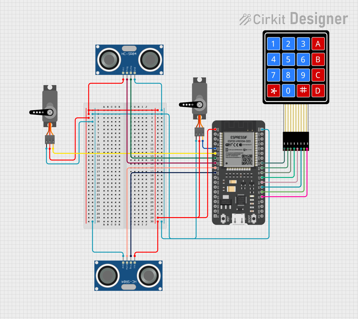
This circuit involves an ESP32 microcontroller interfacing with two HC-SR04 ultrasonic sensors, two servos, and a 4x4 membrane matrix keypad. The ESP32 controls the servos and reads data from the ultrasonic sensors and keypad. The circuit is designed to demonstrate basic sensor integration and actuator control using the ESP32.
Component List
ESP32 - 38 pins
- Description: A powerful microcontroller with built-in Wi-Fi and Bluetooth capabilities.
- Pins: 3V3, EN, SP, SN, G34, G35, G32, G33, G25, G26, G27, G14, G12, GND, G13, SD2, SD3, CMD, 5V, G23, G22, TXD, RXD, G21, G19, G18, G5, G17, G16, G4, G0, G2, G15, SD1, SD0, CLK
HC-SR04 Ultrasonic Sensor
- Description: A sensor used to measure distance by using ultrasonic waves.
- Pins: VCC, TRIG, ECHO, GND
Servo
- Description: A motor that can be controlled to move to a specific position.
- Pins: GND, VCC, PWM
4X4 Membrane Matrix Keypad
- Description: A keypad with 16 buttons arranged in a 4x4 matrix.
- Pins: R1, R2, R3, R4, C1, C2, C3, C4
Wiring Details
ESP32 - 38 pins
- 3V3: Connected to VCC of both HC-SR04 Ultrasonic Sensors and both Servos.
- GND: Connected to GND of both HC-SR04 Ultrasonic Sensors and both Servos.
- G35: Connected to PWM of the first Servo.
- G34: Connected to PWM of the second Servo.
- G33: Connected to TRIG of the first HC-SR04 Ultrasonic Sensor.
- G32: Connected to ECHO of the first HC-SR04 Ultrasonic Sensor.
- G26: Connected to TRIG of the second HC-SR04 Ultrasonic Sensor.
- G25: Connected to ECHO of the second HC-SR04 Ultrasonic Sensor.
- G19: Connected to R1 of the 4X4 Membrane Matrix Keypad.
- G18: Connected to R2 of the 4X4 Membrane Matrix Keypad.
- G5: Connected to R3 of the 4X4 Membrane Matrix Keypad.
- G17: Connected to R4 of the 4X4 Membrane Matrix Keypad.
- G16: Connected to C1 of the 4X4 Membrane Matrix Keypad.
- G4: Connected to C2 of the 4X4 Membrane Matrix Keypad.
- G0: Connected to C3 of the 4X4 Membrane Matrix Keypad.
- G2: Connected to C4 of the 4X4 Membrane Matrix Keypad.
HC-SR04 Ultrasonic Sensor (First)
- VCC: Connected to 3V3 of the ESP32.
- GND: Connected to GND of the ESP32.
- TRIG: Connected to G33 of the ESP32.
- ECHO: Connected to G32 of the ESP32.
HC-SR04 Ultrasonic Sensor (Second)
- VCC: Connected to 3V3 of the ESP32.
- GND: Connected to GND of the ESP32.
- TRIG: Connected to G26 of the ESP32.
- ECHO: Connected to G25 of the ESP32.
Servo (First)
- VCC: Connected to 3V3 of the ESP32.
- GND: Connected to GND of the ESP32.
- PWM: Connected to G35 of the ESP32.
Servo (Second)
- VCC: Connected to 3V3 of the ESP32.
- GND: Connected to GND of the ESP32.
- PWM: Connected to G34 of the ESP32.
4X4 Membrane Matrix Keypad
- R1: Connected to G19 of the ESP32.
- R2: Connected to G18 of the ESP32.
- R3: Connected to G5 of the ESP32.
- R4: Connected to G17 of the ESP32.
- C1: Connected to G16 of the ESP32.
- C2: Connected to G4 of the ESP32.
- C3: Connected to G0 of the ESP32.
- C4: Connected to G2 of the ESP32.
Code Documentation
ESP32 Code (sketch.ino)
void setup() {
  // put your setup code here, to run once:

}

void loop() {
  // put your main code here, to run repeatedly:

}
This code is a basic template for the ESP32 microcontroller. The setup() function is where you initialize your components and configurations, and the loop() function is where you place the main logic that runs repeatedly.
Additional Documentation (documentation.txt)
This file is currently empty and can be used to add further documentation or notes about the project.