
Arduino UNO Controlled Air Quality Monitoring System with Servo Adjustment and LCD Display
View and Edit Project In Cirkit Designer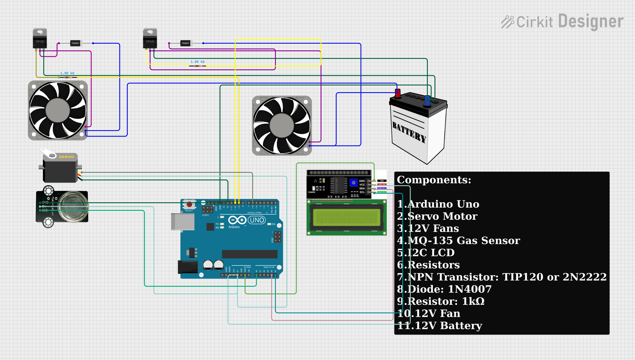
Circuit Documentation
Summary
This circuit is designed to interface various components with an Arduino UNO microcontroller. It includes input and output devices such as an LCD I2C Display, a Servo motor, and an MQ-135 Air Quality Sensor. The circuit also incorporates power management components like a 12V Battery, TIP120 Hi-Current Darlington Transistors, and 1N4007 Rectifier Diodes to drive two 12V Fans. Resistors are used for current limiting and pull-up/down configurations. The Arduino UNO serves as the central processing unit, controlling the Servo and reading sensor data, as well as communicating with the LCD display.
Component List
- 40 Fan 12v: A 12V fan used for cooling or ventilation purposes.
- Resistor: A 1000 Ohm resistor, typically used for current limiting or voltage division.
- Servo: A motor capable of precise position control, used for actuation in the circuit.
- MKE-S09 MQ-135 Air Quality Sensor: A sensor for detecting various gases in the air, providing an analog signal output.
- TIP120 Hi-Current Darlington Transistor: A transistor used for switching high-current loads.
- 1N4007 Rectifier Diode: A diode used for preventing reverse current flow and protecting components from voltage spikes.
- Arduino UNO: A microcontroller board based on the ATmega328P, used for controlling the circuit's logic and processing sensor data.
- LCD I2C Display: A display module for showing information, interfaced with the Arduino via the I2C protocol.
- 12V Battery: A power source for the circuit, providing 12V.
Wiring Details
40 Fan 12v
- +12V: Connected to the 12V Battery VCC and the Cathode of the 1N4007 Rectifier Diode.
- -12V: Connected to the Collector of the TIP120 Hi-Current Darlington Transistor.
Resistor (1000 Ohms)
- pin1: Connected to the Base of the TIP120 Hi-Current Darlington Transistor.
- pin2: Connected to the Arduino UNO Digital Pins (D10 or D9, depending on the instance).
Servo
- gnd: Connected to the 12V Battery GND.
- vcc: Connected to the Arduino UNO 5V pin.
- pulse: Connected to the Arduino UNO Digital Pin D6.
MKE-S09 MQ-135 Air Quality Sensor
- GND: Connected to the 12V Battery GND.
- 5V: Connected to the Arduino UNO 5V pin.
- SIG: Connected to the Arduino UNO Analog Pin A0.
TIP120 Hi-Current Darlington Transistor
- BASE: Connected to the corresponding Resistor pin1.
- COLLECTOR: Connected to the -12V pin of the 40 Fan 12v.
- EMITTER: Connected to the 12V Battery GND.
1N4007 Rectifier Diode
- Cathode: Connected to the 12V Battery VCC.
- Anode: Connected to the Collector of the TIP120 Hi-Current Darlington Transistor.
Arduino UNO
- GND: Connected to the 12V Battery GND.
- 5V: Connected to the VCC pins of the Servo, LCD I2C Display, and MQ-135 Air Quality Sensor.
- A0: Connected to the SIG pin of the MQ-135 Air Quality Sensor.
- A4 (SDA): Connected to the SDA pin of the LCD I2C Display.
- A5 (SCL): Connected to the SCL pin of the LCD I2C Display.
- D6: Connected to the pulse pin of the Servo.
- D9/D10: Connected to the pin2 of the corresponding Resistor.
LCD I2C Display
- GND: Connected to the Arduino UNO GND pin.
- VCC: Connected to the Arduino UNO 5V pin.
- SDA: Connected to the Arduino UNO A4 (SDA) pin.
- SCL: Connected to the Arduino UNO A5 (SCL) pin.
12V Battery
- GND: Connected to the EMITTER of the TIP120 Hi-Current Darlington Transistors and the GND of the Servo, Arduino UNO, and MQ-135 Air Quality Sensor.
- VCC: Connected to the +12V pin of the 40 Fan 12v and the Cathode of the 1N4007 Rectifier Diodes.
Documented Code
Arduino UNO Code (sketch.ino)
void setup() {
  // put your setup code here, to run once:

}

void loop() {
  // put your main code here, to run repeatedly:

}
This code template is a starting point for the Arduino UNO microcontroller. The setup() function is called once when the microcontroller is powered on or reset. It is used to initialize variables, pin modes, start using libraries, etc. The loop() function is called repeatedly and contains the main logic of the program. It is where the microcontroller reads sensors, controls actuators, and communicates with other devices like the LCD display.
The actual implementation details would be added to these functions based on the specific requirements of the circuit's operation.