
LED Indicator Circuit with Push Switches and Voltage Regulation
View and Edit Project In Cirkit Designer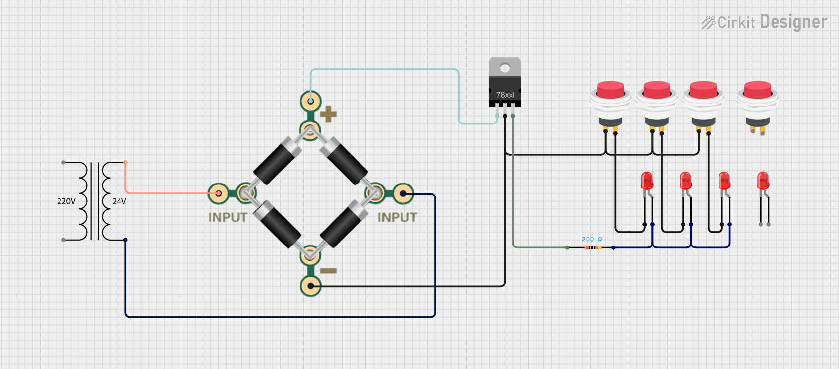
Circuit Documentation
Summary
This circuit consists of multiple red LEDs, resistors, push switches, a bridge rectifier, a power transformer, and a voltage regulator. The circuit is designed to control the illumination of LEDs using push switches. The power is regulated and rectified to ensure stable operation of the LEDs.
Component List
LED: Two Pin (red)
- Description: A standard red LED with two pins: cathode and anode.
- Pins: cathode, anode
Resistor
- Description: A resistor with a resistance of 200 Ohms.
- Pins: pin1, pin2
- Properties:
- Resistance: 200 Ohms
2Pin Push Switch
- Description: A push switch with two pins: Input + and Output +.
- Pins: Input +, Output +
BRIDGE - 1N4007
- Description: A bridge rectifier with four pins: 1 INPUT, 2 INPUT, + PIN, - PIN.
- Pins: 1 INPUT, 2 INPUT, + PIN, - PIN
Power Transformer (220V to 24V)
- Description: A power transformer that steps down 220V to 24V.
- Pins: 2 - Primary, 1 - Primary, 3 - Secondary, 4 - Secondary
Voltage Regulator
- Description: A voltage regulator with three pins: IN, GND, OUT.
- Pins: IN, GND, OUT
Wiring Details
LED: Two Pin (red)
Cathode connected to:
- Output + of 2Pin Push Switch
- Cathode of another LED
Anode connected to:
- Anode of other LEDs
- Pin2 of Resistor
Resistor
Pin1 connected to:
- OUT of Voltage Regulator
Pin2 connected to:
- Anode of LEDs
2Pin Push Switch
Input + connected to:
-
- PIN of BRIDGE - 1N4007
- GND of Voltage Regulator
-
Output + connected to:
- Cathode of LEDs
BRIDGE - 1N4007
1 INPUT connected to:
- 3 - Secondary of Power Transformer
2 INPUT connected to:
- 4 - Secondary of Power Transformer
+ PIN connected to:
- IN of Voltage Regulator
- PIN connected to:
- Input + of 2Pin Push Switch
Power Transformer (220V to 24V)
3 - Secondary connected to:
- 1 INPUT of BRIDGE - 1N4007
4 - Secondary connected to:
- 2 INPUT of BRIDGE - 1N4007
Voltage Regulator
IN connected to:
-
- PIN of BRIDGE - 1N4007
-
GND connected to:
- Input + of 2Pin Push Switch
OUT connected to:
- Pin1 of Resistor
Code
There is no microcontroller code associated with this circuit.