
Circuit Documentation
Summary
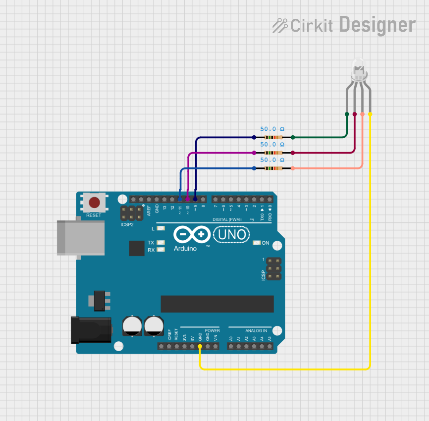
This circuit features a common cathode RGB LED controlled by an Arduino UNO. The RGB LED is connected through a series of resistors to limit the current flowing through each color channel (Red, Green, and Blue). The Arduino UNO is programmed to cycle through various colors and effects, demonstrating the capabilities of PWM (Pulse Width Modulation) to control the brightness of each LED channel.
Component List
1. RGB Light (Common Cathode)
- Description: A common cathode RGB LED that combines red, green, and blue light to create various colors.
- Pins:
- R (Red)
- G (Green)
- B (Blue)
-
- (Common Cathode)
2. Arduino UNO
- Description: A microcontroller board based on the ATmega328P. It is used to control the RGB LED and execute the programmed logic.
- Pins:
- Digital I/O pins (D0-D13)
- Analog input pins (A0-A5)
- Power pins (GND, 5V, Vin)
3. Resistor (50 Ohms)
- Description: A resistor used to limit the current flowing through the red channel of the RGB LED.
- Pins:
- pin1
- pin2
4. Resistor (50 Ohms)
- Description: A resistor used to limit the current flowing through the green channel of the RGB LED.
- Pins:
- pin1
- pin2
5. Resistor (50 Ohms)
- Description: A resistor used to limit the current flowing through the blue channel of the RGB LED.
- Pins:
- pin1
- pin2
Wiring Details
RGB Light (Common Cathode)
- R Pin: Connected to pin2 of the first resistor (50 Ohms).
- G Pin: Connected to pin2 of the second resistor (50 Ohms).
- B Pin: Connected to pin2 of the third resistor (50 Ohms).
- - Pin: Connected to GND of the Arduino UNO.
Arduino UNO
- GND Pin: Connected to the - pin of the RGB Light (Common Cathode).
- D11 Pin: Connected to pin1 of the third resistor (50 Ohms).
- D10 Pin: Connected to pin1 of the second resistor (50 Ohms).
- D9 Pin: Connected to pin1 of the first resistor (50 Ohms).
Resistor (50 Ohms) - Red Channel
- pin1: Connected to D9 of the Arduino UNO.
- pin2: Connected to the R pin of the RGB Light (Common Cathode).
Resistor (50 Ohms) - Green Channel
- pin1: Connected to D10 of the Arduino UNO.
- pin2: Connected to the G pin of the RGB Light (Common Cathode).
Resistor (50 Ohms) - Blue Channel
- pin1: Connected to D11 of the Arduino UNO.
- pin2: Connected to the B pin of the RGB Light (Common Cathode).
Documented Code
// Common-cathode RGB LED: R=9, G=10, B=11
const int Rpin = 9;
const int Gpin = 10;
const int Bpin = 11;

void setup() {
  pinMode(Rpin, OUTPUT);
  pinMode(Gpin, OUTPUT);
  pinMode(Bpin, OUTPUT);
  // Start off
  setRGB(0,0,0);
}

void loop() {
  // Quick channel check
  setRGB(255, 0, 0); delay(500); // Red
  setRGB(0, 255, 0); delay(500); // Green
  setRGB(0, 0, 255); delay(500); // Blue

  // Basic mixes
  setRGB(255, 255, 0); delay(500); // Yellow
  setRGB(0, 255, 255); delay(500); // Cyan
  setRGB(255, 0, 255); delay(500); // Magenta
  setRGB(255, 255, 255); delay(700); // White

  // Smooth white fade up/down
  for (int i = 0; i <= 255; i++) { setRGB(i, i, i); delay(6); }
  for (int i = 255; i >= 0; i--) { setRGB(i, i, i); delay(6); }

  // Smooth rainbow-ish sweep (blend R->G->B)
  for (int i = 0; i <= 255; i++) { setRGB(255 - i, i, 0); delay(5); }   // R->G
  for (int i = 0; i <= 255; i++) { setRGB(0, 255 - i, i); delay(5); }   // G->B
  for (int i = 0; i <= 255; i++) { setRGB(i, 0, 255 - i); delay(5); }   // B->R
}

void setRGB(uint8_t r, uint8_t g, uint8_t b) {
  // Common-cathode: direct PWM
  analogWrite(Rpin, r);
  analogWrite(Gpin, g);
  analogWrite(Bpin, b);
}
This documentation provides a comprehensive overview of the circuit, detailing each component, its connections, and the code used to control the RGB LED.