
Circuit Documentation
Summary of the Circuit
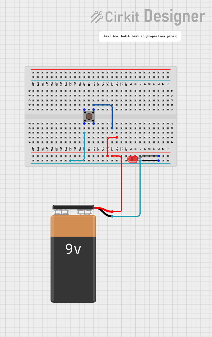
This circuit consists of a simple LED control mechanism powered by a 9V battery. The LED is designed to light up when the pushbutton is engaged. The components include a 9V battery, a red two-pin LED, and a pushbutton. There is no microcontroller involved in this circuit, and thus no embedded code is required for its operation.
Component List
9V Battery
- Description: A standard 9V battery providing the power source for the circuit.
- Pins: Negative (-) and Positive (+)
LED: Two Pin (red)
- Description: A red light-emitting diode (LED) that lights up when powered.
- Pins: Cathode (-), Anode (+)
Pushbutton
- Description: A momentary pushbutton switch used to control the flow of electricity to the LED.
- Pins: Pin 3 (out), Pin 4 (out), Pin 1 (in), Pin 2 (in)
Wiring Details
9V Battery
- Negative (-): Connected to the cathode of the LED and Pin 2 (in) of the Pushbutton.
- Positive (+): Connected to the anode of the LED.
LED: Two Pin (red)
- Cathode: Connected to the negative (-) terminal of the 9V Battery and Pin 2 (in) of the Pushbutton.
- Anode: Connected to the positive (+) terminal of the 9V Battery.
Pushbutton
- Pin 3 (out): Not connected in this circuit.
- Pin 4 (out): Not connected in this circuit.
- Pin 1 (in): Not connected in this circuit.
- Pin 2 (in): Connected to the cathode of the LED and the negative (-) terminal of the 9V Battery.
Documented Code
There is no microcontroller or embedded code associated with this circuit as per the provided information. Therefore, no code documentation is necessary for this circuit's operation.
Note: The circuit documentation provided is based on the inputs given and does not include instance IDs as per the request. The circuit appears to be a simple LED circuit with a pushbutton switch and does not involve any programmable devices.