Arduino Nano-Controlled Distance Measurement and Display with Servo Feedback
Circuit Documentation
Summary
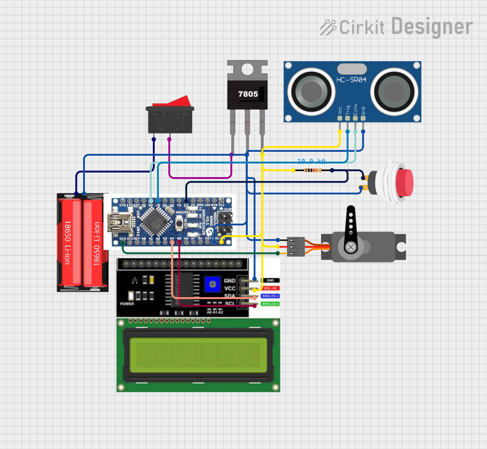
This circuit is designed to interface an Arduino Nano with various components including a 18650 Li-Ion battery, a rocker switch, an LCD I2C display, a servo motor, a 7805 voltage regulator, a push switch, and an HC-SR04 ultrasonic sensor. The circuit is powered by the 18650 Li-Ion battery, which is controlled by the rocker switch. The Arduino Nano serves as the central processing unit, controlling the servo motor, reading data from the ultrasonic sensor, and displaying information on the LCD. The 7805 voltage regulator ensures that the components receive a stable 5V supply. The push switch is used as an input device, and its state is read by the Arduino Nano.
Component List
- 18650 Li-Ion Battery: Provides the power source for the circuit.
- Rocker Switch: Controls the power supply to the circuit.
- Arduino Nano: The microcontroller that manages the logic and controls the other components.
- LCD I2C Display: Displays information and is controlled by the Arduino Nano via I2C communication.
- Servo Motor: An actuator that is controlled by the Arduino Nano.
- 7805 Voltage Regulator: Regulates the input voltage to a stable 5V output for the circuit.
- 2Pin Push Switch: Serves as a user input that can be read by the Arduino Nano.
- HC-SR04 Ultrasonic Sensor: Measures distances and sends the data to the Arduino Nano.
- Resistor (10k Ohms): Used for pull-up or pull-down resistances to ensure proper logic levels.
Wiring Details
18650 Li-Ion Battery
- Positive: Connected to the rocker switch.
- Negative: Common ground with the LCD I2C display, HC-SR04 ultrasonic sensor, push switch, Arduino Nano, servo motor, and 7805 voltage regulator.
Rocker Switch
- Pin 1: Connected to the positive terminal of the 18650 Li-Ion battery.
- Pin 2: Connected to the Vin pin of the 7805 voltage regulator.
Arduino Nano
- D12 - D2: Not connected.
- GND: Common ground with other components.
- RST, RX0, TX1: Not connected.
- D13: Connected to the PWM pin of the servo motor.
- 3V3, REF, A0, A1, A3: Not connected.
- A4 (SDA): Connected to the SDA pin of the LCD I2C display.
- A5 (SCL): Connected to the SCL pin of the LCD I2C display.
- A6, A7: Not connected.
- 5V: Not connected.
- VIN: Connected to the Vout pin of the 7805 voltage regulator.
LCD I2C Display
- GND: Common ground.
- VCC: Connected to the Vout pin of the 7805 voltage regulator.
- SDA: Connected to the A4 pin of the Arduino Nano.
- SCL: Connected to the A5 pin of the Arduino Nano.
Servo Motor
- GND: Common ground.
- VCC: Connected to the Vout pin of the 7805 voltage regulator.
- PWM: Connected to the D13 pin of the Arduino Nano.
7805 Voltage Regulator
- Vin: Connected to the rocker switch.
- Gnd: Common ground.
- Vout: Connected to the VCC pins of the LCD I2C display, HC-SR04 ultrasonic sensor, Arduino Nano, and servo motor.
2Pin Push Switch
- Input +: Connected to the pin2 of the resistor and D3 pin of the Arduino Nano.
- Output +: Common ground.
HC-SR04 Ultrasonic Sensor
- VCC: Connected to the Vout pin of the 7805 voltage regulator.
- TRIG: Connected to the D7 pin of the Arduino Nano.
- ECHO: Connected to the D8 pin of the Arduino Nano.
- GND: Common ground.
Resistor (10k Ohms)
- pin1: Connected to the VCC pins of the LCD I2C display, HC-SR04 ultrasonic sensor, Arduino Nano, and servo motor.
- pin2: Connected to the Input + pin of the push switch and D3 pin of the Arduino Nano.
Documented Code
Since no code was provided in the input, this section is left blank. Normally, this section would include the source code for the microcontroller, along with comments explaining the functionality of the code and how it interacts with the connected components.