
Arduino UNO-Based Environmental Monitoring and Control System with GSM Notification
View and Edit Project In Cirkit Designer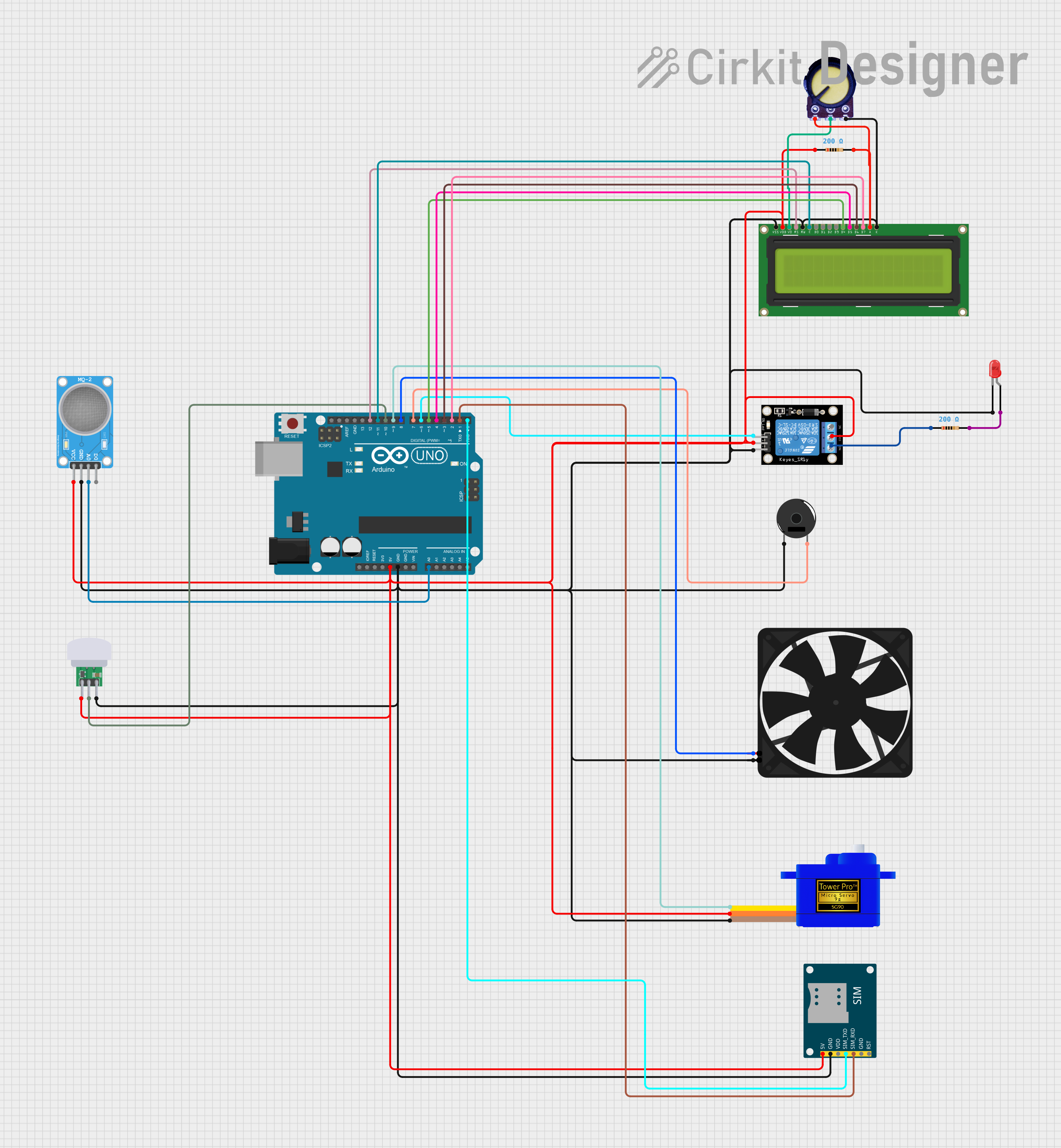
Circuit Documentation
Summary
This document provides a detailed overview of a circuit that includes various components such as sensors, actuators, a microcontroller, and other peripheral devices. The central component of the circuit is an Arduino UNO microcontroller, which interfaces with a fan, a servomotor, a piezo buzzer, a relay module, an LCD display, a potentiometer, an LED, resistors, an MQ-2 sensor, a PIR sensor, and a SIM800L GSM module. The circuit is designed to perform multiple functions, which could range from sensing environmental parameters to displaying information and controlling actuators based on sensor inputs.
Component List
- Arduino UNO: A microcontroller board based on the ATmega328P, featuring digital and analog I/O pins.
- Fan: A device powered by a 5V supply to create airflow.
- Servomotor SG90: A small and lightweight servo used for precise control of motion.
- Piezo Buzzer: An electronic device that produces sound when an electric signal is applied.
- KY-019 Relay Module 1 Channel: A relay module for controlling high power/high voltage devices.
- LCD Display 16x2: A liquid crystal display capable of displaying 16 characters per line across 2 lines.
- Potentiometer: A three-terminal resistor with a rotating contact that forms an adjustable voltage divider.
- LED (Red): A two-pin light-emitting diode that emits red light.
- Resistor: A passive two-terminal electrical component that implements electrical resistance as a circuit element.
- MQ-2 Sensor: A gas sensor used for detecting a variety of gases including LPG, smoke, and alcohol vapor.
- PIR Sensor SB312A: A passive infrared sensor that detects motion by measuring changes in the infrared levels emitted by surrounding objects.
- SIM800L GSM Module: A module that allows GSM/GPRS communication and supports voice calls, SMS messages, and data transmission.
Wiring Details
Arduino UNO
- 5V: Connected to VCC of various components for power supply.
- GND: Common ground for various components.
- A0: Connected to the A0 pin of the MQ-2 sensor.
- D12: Connected to the RS pin of the LCD Display.
- D11: Connected to the E pin of the LCD Display.
- D10: Connected to the OUT pin of the PIR Sensor.
- D9: Connected to the SIG pin of the Servomotor.
- D8: Connected to the 5V pin of the Fan.
- D7: Connected to pin 2 of the Piezo Buzzer.
- D6: Connected to the S pin of the Relay Module.
- D5-D2: Connected to DB4-DB7 pins of the LCD Display.
- D1: Connected to the SIM_RXD pin of the SIM800L GSM Module.
- D0: Connected to the SIM_TXD pin of the SIM800L GSM Module.
Fan
- 5V: Powered by the Arduino UNO.
- GND: Connected to the common ground.
Servomotor SG90
- SIG: Controlled by D9 on the Arduino UNO.
- VCC: Powered by the 5V supply from the Arduino UNO.
- GND: Connected to the common ground.
Piezo Buzzer
- Pin 1: Connected to the common ground.
- Pin 2: Controlled by D7 on the Arduino UNO.
KY-019 Relay Module 1 Channel
- S: Controlled by D6 on the Arduino UNO.
- 5V: Powered by the Arduino UNO.
- GND: Connected to the common ground.
- NO: Connected to one terminal of a resistor.
- COM: Connected to the 5V supply.
LCD Display 16x2
- LEDK, RW, VSS: Connected to the common ground.
- LEDA: Connected to the potentiometer and a resistor for backlight control.
- DB7-DB4: Controlled by D2-D5 on the Arduino UNO.
- E: Controlled by D11 on the Arduino UNO.
- RS: Controlled by D12 on the Arduino UNO.
- VO: Connected to the output of the potentiometer for contrast control.
- VDD: Powered by the 5V supply from the Arduino UNO.
Potentiometer
- GND: Connected to the common ground and one terminal of a resistor.
- Output: Connected to the VO pin of the LCD Display for contrast control.
- VCC: Powered by the 5V supply from the Arduino UNO.
LED (Red)
- Cathode: Connected to the common ground.
- Anode: Connected to one terminal of a resistor.
Resistor
- Pin1: Connected to the 5V supply and various VCC pins of components.
- Pin2: Connected to the anode of the LED and the NO pin of the Relay Module.
MQ-2 Sensor
- VCC: Powered by the 5V supply from the Arduino UNO.
- GND: Connected to the common ground.
- A0: Connected to the A0 pin of the Arduino UNO.
PIR Sensor SB312A
- VCC: Powered by the 5V supply from the Arduino UNO.
- OUT: Connected to D10 on the Arduino UNO.
- GND: Connected to the common ground.
SIM800L GSM Module
- 5V: Powered by the 5V supply from the Arduino UNO.
- GND: Connected to the common ground.
- SIM_RXD: Connected to D1 on the Arduino UNO.
- SIM_TXD: Connected to D0 on the Arduino UNO.
Documented Code
Arduino UNO Code (sketch.ino)
void setup() {
  // put your setup code here, to run once:

}

void loop() {
  // put your main code here, to run repeatedly:

}
Note: The provided code is a template and does not contain any functional code. It is expected that the user will add the necessary setup and loop code to control the components as per the requirements of the circuit's application.