
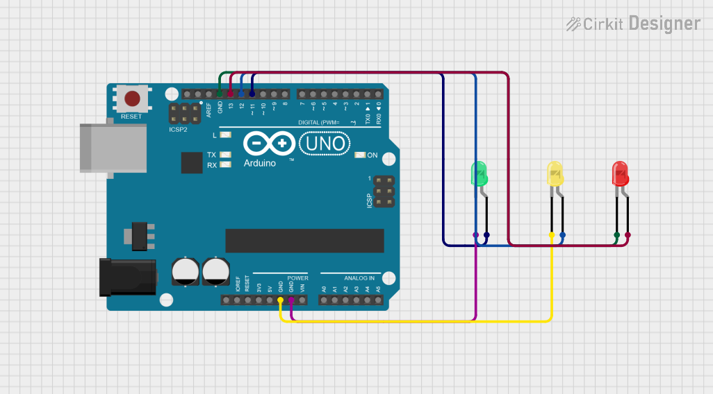
Traffic Light Simulation Circuit Documentation
Summary
This circuit is designed to simulate a traffic light using an Arduino UNO microcontroller and three LEDs (red, yellow, and green). The Arduino UNO controls the state of each LED to mimic the behavior of a traffic light: the red LED lights up for 6 seconds, the yellow LED for 2 seconds, and the green LED for 20 seconds. This sequence repeats indefinitely.
Component List
Arduino UNO
- Description: A microcontroller board based on the ATmega328P.
- Purpose: Acts as the central controller for the traffic light simulation, driving the LEDs in a timed sequence.
LED: Two Pin (red)
- Description: A standard red LED.
- Purpose: Represents the stop signal in the traffic light simulation.
LED: Two Pin (green)
- Description: A standard green LED.
- Purpose: Represents the go signal in the traffic light simulation.
LED: Two Pin (yellow)
- Description: A standard yellow LED.
- Purpose: Represents the caution signal in the traffic light simulation.
Wiring Details
Arduino UNO
- Digital Pin 13: Connected to the anode of the red LED.
- Digital Pin 12: Connected to the anode of the yellow LED.
- Digital Pin 11: Connected to the anode of the green LED.
- GND: Connected to the cathodes of the red, yellow, and green LEDs.
LED: Two Pin (red)
- Anode: Connected to Digital Pin 13 on the Arduino UNO.
- Cathode: Connected to GND on the Arduino UNO.
LED: Two Pin (green)
- Anode: Connected to Digital Pin 11 on the Arduino UNO.
- Cathode: Connected to GND on the Arduino UNO.
LED: Two Pin (yellow)
- Anode: Connected to Digital Pin 12 on the Arduino UNO.
- Cathode: Connected to GND on the Arduino UNO.
Documented Code
/*
 * This Arduino sketch controls three LEDs (red, yellow, green) connected to
 * an Arduino UNO to simulate a traffic light. The red LED is on for 6 seconds,
 * the yellow LED is on for 2 seconds, and the green LED is on for 20 seconds.
 */

// Pin definitions
const int redLEDPin = 13;
const int yellowLEDPin = 12;
const int greenLEDPin = 11;

void setup() {
  // Initialize the LED pins as outputs
  pinMode(redLEDPin, OUTPUT);
  pinMode(yellowLEDPin, OUTPUT);
  pinMode(greenLEDPin, OUTPUT);
}

void loop() {
  // Turn on the red LED
  digitalWrite(redLEDPin, HIGH);
  delay(6000); // Wait for 6 seconds
  digitalWrite(redLEDPin, LOW);

  // Turn on the yellow LED
  digitalWrite(yellowLEDPin, HIGH);
  delay(2000); // Wait for 2 seconds
  digitalWrite(yellowLEDPin, LOW);

  // Turn on the green LED
  digitalWrite(greenLEDPin, HIGH);
  delay(20000); // Wait for 20 seconds
  digitalWrite(greenLEDPin, LOW);
}
The code is written for the Arduino UNO and is responsible for controlling the timing and state of each LED to simulate a traffic light pattern. The setup() function initializes the LED pins as outputs, and the loop() function contains the logic to turn each LED on and off in the correct sequence.