
Wi-Fi Controlled Smart Irrigation System with ESP8266 and Soil Moisture Sensor
View and Edit Project In Cirkit Designer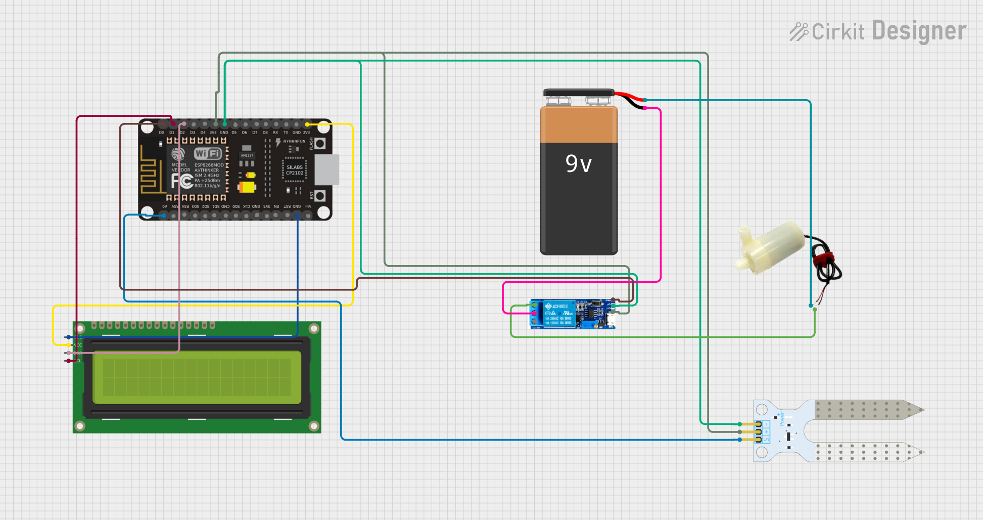
Circuit Documentation
Summary
This circuit is designed to monitor soil moisture levels and control a water pump based on the moisture readings. It uses an ESP8266 NodeMCU microcontroller to read data from a soil moisture sensor and display the information on a 16x2 I2C LCD. The microcontroller also controls a relay module to turn the water pump on or off based on the soil moisture levels. The system is connected to the internet via Wi-Fi and can be monitored and controlled using the Blynk app.
Component List
ESP8266 NodeMCU
- Description: A low-cost Wi-Fi microcontroller with GPIO, ADC, and PWM capabilities.
- Pins: D0, D1, D2, D3, D4, 3V3, GND, D5, D6, D7, D8, RX, TX, A0, RSV, SD3, SD2, SD1, CMD, SD0, CLK, EN, RST, VIN
16x2 I2C LCD
- Description: A 16x2 character LCD display with I2C interface.
- Pins: GND, VCC, SDA, SCL
5V Mini Water Pump
- Description: A small water pump operating at 5V.
- Pins: Positive pin, Negative pin
Relay Module 5V-30V
- Description: A relay module that can be triggered by a 5V signal to switch higher voltage loads.
- Pins: Common contact, Normally open, Normally closed, Trigger, V-, V+
9V Battery
- Description: A standard 9V battery for powering the water pump.
- Pins: +, -
Soil Moisture Sensor
- Description: A sensor to measure the moisture content in the soil.
- Pins: VCC, GND, SIG
Wiring Details
ESP8266 NodeMCU
- D0: Connected to Relay module (Trigger)
- D1: Connected to 16x2 I2C LCD (SCL)
- D2: Connected to 16x2 I2C LCD (SDA)
- 3V3: Connected to Relay module (V+), Soil Moisture Sensor (VCC), and 16x2 I2C LCD (VCC)
- GND: Connected to Relay module (V-), Soil Moisture Sensor (GND), and 16x2 I2C LCD (GND)
- A0: Connected to Soil Moisture Sensor (SIG)
16x2 I2C LCD
- GND: Connected to ESP8266 NodeMCU (GND)
- VCC: Connected to ESP8266 NodeMCU (3V3)
- SDA: Connected to ESP8266 NodeMCU (D2)
- SCL: Connected to ESP8266 NodeMCU (D1)
5V Mini Water Pump
- Positive pin: Connected to 9V Battery (+)
- Negative pin: Connected to Relay module (Normally open)
Relay Module 5V-30V
- Common contact: Connected to 9V Battery (-)
- Normally open: Connected to 5V Mini Water Pump (Negative pin)
- Trigger: Connected to ESP8266 NodeMCU (D0)
- V-: Connected to ESP8266 NodeMCU (GND)
- V+: Connected to ESP8266 NodeMCU (3V3)
9V Battery
- +: Connected to 5V Mini Water Pump (Positive pin)
- -: Connected to Relay module (Common contact)
Soil Moisture Sensor
- VCC: Connected to ESP8266 NodeMCU (3V3)
- GND: Connected to ESP8266 NodeMCU (GND)
- SIG: Connected to ESP8266 NodeMCU (A0)
Documented Code
#define BLYNK_TEMPLATE_ID "TMPL6mU3PuwAw"
#define BLYNK_TEMPLATE_NAME "MyProject"
#define BLYNK_PRINT Serial
#include <LiquidCrystal_I2C.h>
#include <ESP8266WiFi.h>
#include <BlynkSimpleEsp8266.h>
#include <DHT.h>
#include <Wire.h>

// Initialize the LCD display
LiquidCrystal_I2C lcd(0x27, 16, 2);
// Wi-Fi credentials
char auth[] = "0C8Pt-X2iftjL3-Gdq9y6Q-WNVJoncjg";
char ssid[] = "mohan";
char pass[] = "1234567890";

BlynkTimer timer;
bool Relay = 0;
bool isBlocked = true;
bool automaticControlEnabled = true;
int value = 0;

// Water pump control pin
#define sensor A0
#define WATER_PUMP_PIN D0
#define SOIL_MOISTURE_THRESHOLD 30  // Adjust this threshold value as needed

// Function prototypes
void soilMoistureSensor();
BLYNK_WRITE(V1);
BLYNK_WRITE(V3);

void setup() {
    Serial.begin(115200);
    pinMode(WATER_PUMP_PIN, OUTPUT);
    digitalWrite(WATER_PUMP_PIN, HIGH);
    lcd.begin();
    lcd.backlight();

    // Connect to Wi-Fi
    WiFi.begin(ssid, pass);
    while (WiFi.status() != WL_CONNECTED) {
        delay(1000);
        Serial.println("Connecting to WiFi...");
    }
    Serial.println("Connected to WiFi");

    // Initialize Blynk
    Blynk.begin(auth, ssid, pass, "blynk.cloud", 80);
    Blynk.virtualWrite(V3, 1);
    lcd.setCursor(1, 0);
    lcd.print("System Loading");
    for (int a = 0; a <= 15; a++) {
      lcd.setCursor(a, 1);
      lcd.print(".");
      delay(500);
    }
    lcd.clear();

    // Call the function
    timer.setInterval(100L, soilMoistureSensor);
}

// Blynk virtual pin handler for water pump control

// Get the soil moisture values
void soilMoistureSensor() {
    int value = analogRead(sensor);
    value = map(value, 0, 1024, 0, 100);
    value = (value - 100) * -1;

    Blynk.virtualWrite(V0, value);
    lcd.setCursor(0, 0);
    lcd.print("Moisture :");
    lcd.print(value);
    lcd.print(" ");
if (automaticControlEnabled) {

    // Check if soil moisture is below the threshold
    if (value < SOIL_MOISTURE_THRESHOLD) {
        // If below threshold, turn on the water pump
        if (!Relay) {
            digitalWrite(WATER_PUMP_PIN, HIGH);  // Assuming LOW activates the relay or pump
            Relay = 1;
            Blynk.virtualWrite(V2, 1);  // Update Blynk app to reflect the pump status
            Serial.println("Water pump turned ON");
        }
    } else {
        // If above or equal to threshold, turn off the water pump
        if (Relay) {
            digitalWrite(WATER_PUMP_PIN, LOW);  // Assuming HIGH deactivates the relay or pump
            Relay = 0;
            Blynk.virtualWrite(V2, 0);  // Update Blynk app to reflect the pump status
            Serial.println("Water pump turned OFF");
        }
    }
}
}
BLYNK_WRITE(V1) {
    // Callback for changes in Button V3 state
    if (isBlocked) {
        // Button V1 is blocked, do nothing
    } else {
        int waterPumpStatus = param.asInt();

        if (waterPumpStatus == 1) {
            digitalWrite(WATER_PUMP_PIN, HIGH);  // Assuming HIGH is ON and LOW is OFF
            Serial.println("Water pump turned ON");
            Blynk.virtualWrite(V2, 1);
        } else {
            digitalWrite(WATER_PUMP_PIN, LOW);   // Assuming HIGH is ON and LOW is OFF
            Serial.println("Water pump turned OFF");
            Blynk.virtualWrite(V2, 0);
        }
    }
}

BLYNK_WRITE(V3) {
    int restartButtonState = param.asInt();

    if (restartButtonState == 1) {
        Serial.println("Restart AUTO MOOD...");
        ESP.restart();
        Blynk.virtualWrite(V3, 1);
        isBlocked = true;
    } else {
        // Callback for changes in Button V3 state
        automaticControlEnabled = param.asInt();
        int enableDisableButtonState = param.asInt();
        automaticControlEnabled = enableDisableButtonState == 1;
        Blynk.virtualWrite(V3, automaticControlEnabled ? 1 : 0);
        Blynk.virtualWrite(V3, 0);
        Blynk.virtualWrite(V2, 0);
        digitalWrite(WATER_PUMP_PIN, LOW);  // Assuming HIGH deactivates the relay or pump
        Relay = 0;
        is