
ESP32-Based Smart Weather Station with Wi-Fi Control and PWM Fan
View and Edit Project In Cirkit Designer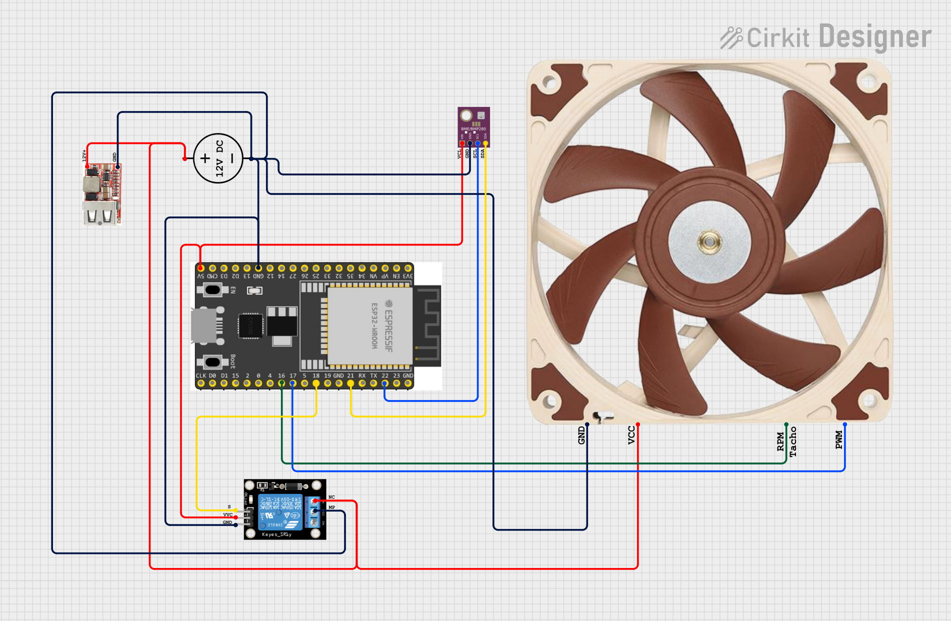
Circuit Documentation
Summary
This circuit involves an ESP32 microcontroller, a BME/BMP280 sensor, a KY-019 relay module, a 12V PWM fan, a DC power source, and a USB regulator. The ESP32 reads data from the BME/BMP280 sensor, controls the relay module, and regulates the fan speed based on temperature readings.
Component List
BME/BMP280
- Description: A sensor module used to measure temperature, humidity, and pressure.
- Pins: GND, SCL, SDA, VIN
ESP32 Wroom Dev Kit
- Description: A development board featuring the ESP32 microcontroller, used for various IoT applications.
- Pins: 3V3, EN, VP, VN, GPIO 34, GPIO 35, GPIO 32, GPIO 33, GPIO 25, GPIO 26, GPIO 27, GPIO 14, GND, GPIO 13, SD2, SD3, CMD, V5, GPIO 23, GPIO 22, TXD, RXD, GPIO 21, GPIO 19, GPIO 18, GPIO 5, GPIO 17, GPIO 16, GPIO 4, GPIO 0, GPIO 2, GPIO 15, SD1, SD0, CLK
DC Power Source
- Description: Provides the necessary power for the circuit.
- Pins: Ground, Positive
KY-019 Relay Module 1 Channel
- Description: A relay module used to control high voltage devices.
- Pins: S, 5V, GND, NC, COM, NO
USB Regulator
- Description: Regulates the voltage from the DC power source to 5V for USB devices.
- Pins: VIN+, VIN-, 5V_USB_VO
12V PWM Fan (120mm)
- Description: A fan used for cooling, controlled via PWM.
- Pins: GND, +12V, TACH, PWM
Wiring Details
BME/BMP280
- GND: Connected to GND of ESP32, DC Power Source, KY-019 Relay Module, USB Regulator, and 12V PWM Fan.
- SCL: Connected to GPIO 22 of ESP32.
- SDA: Connected to GPIO 21 of ESP32.
- VIN: Connected to V5 of ESP32 and 5V of KY-019 Relay Module.
ESP32 Wroom Dev Kit
- GND: Connected to GND of DC Power Source, KY-019 Relay Module, USB Regulator, BME/BMP280, and 12V PWM Fan.
- GPIO 22: Connected to SCL of BME/BMP280.
- GPIO 21: Connected to SDA of BME/BMP280.
- V5: Connected to VIN of BME/BMP280 and 5V of KY-019 Relay Module.
- GPIO 18: Connected to S of KY-019 Relay Module.
- GPIO 17: Connected to PWM of 12V PWM Fan.
- GPIO 16: Connected to TACH of 12V PWM Fan.
DC Power Source
- Ground: Connected to GND of ESP32, KY-019 Relay Module, USB Regulator, BME/BMP280, and 12V PWM Fan.
- Positive: Connected to NC of KY-019 Relay Module, VIN+ of USB Regulator, and +12V of 12V PWM Fan.
KY-019 Relay Module 1 Channel
- GND: Connected to GND of ESP32, DC Power Source, USB Regulator, BME/BMP280, and 12V PWM Fan.
- 5V: Connected to V5 of ESP32 and VIN of BME/BMP280.
- S: Connected to GPIO 18 of ESP32.
- NC: Connected to Positive of DC Power Source.
- COM: Connected to GND of ESP32, DC Power Source, USB Regulator, BME/BMP280, and 12V PWM Fan.
USB Regulator
- VIN+: Connected to Positive of DC Power Source.
- VIN-: Connected to GND of ESP32, DC Power Source, KY-019 Relay Module, BME/BMP280, and 12V PWM Fan.
- 5V_USB_VO: Not connected in this circuit.
12V PWM Fan (120mm)
- GND: Connected to GND of ESP32, DC Power Source, KY-019 Relay Module, USB Regulator, and BME/BMP280.
- +12V: Connected to Positive of DC Power Source.
- TACH: Connected to GPIO 16 of ESP32.
- PWM: Connected to GPIO 17 of ESP32.
Documented Code
sketch.ino
#include <Wire.h>
#include <Adafruit_Sensor.h>
#include <Adafruit_BME280.h>

// Pin Definitionen
#define BME_SDA 21
#define BME_SCL 22
#define RELAY_PIN 18
#define FAN_PWM_PIN 17
#define FAN_TACH_PIN 16

Adafruit_BME280 bme; // BME280 Objekt

void setup() {
  Serial.begin(115200);

  // I2C Initialisierung
  Wire.begin(BME_SDA, BME_SCL);

  // BME280 Initialisierung
  if (!bme.begin(0x76)) {
    Serial.println("BME280 Sensor nicht gefunden!");
    while (1);
  }

  // Relais und Lüfter Pins initialisieren
  pinMode(RELAY_PIN, OUTPUT);
  pinMode(FAN_PWM_PIN, OUTPUT);
  pinMode(FAN_TACH_PIN, INPUT);

  // Relais und Lüfter initial ausschalten
  digitalWrite(RELAY_PIN, LOW);
  ledcAttachPin(FAN_PWM_PIN, 0); // Attach pin to channel 0
  ledcSetup(0, 5000, 8); // 5 kHz PWM, 8-bit resolution
  ledcWrite(0, 0);
}

void loop() {
  // Sensorwerte auslesen
  float temperature = bme.readTemperature();
  float humidity = bme.readHumidity();
  float pressure = bme.readPressure() / 100.0F;

  // Sensorwerte ausgeben
  Serial.print("Temperatur: ");
  Serial.print(temperature);
  Serial.println(" °C");

  Serial.print("Luftfeuchtigkeit: ");
  Serial.print(humidity);
  Serial.println(" %");

  Serial.print("Luftdruck: ");
  Serial.print(pressure);
  Serial.println(" hPa");

  // Relais steuern (Beispiel: Relais einschalten, wenn Temperatur über 25°C)
  if (temperature > 25.0) {
    digitalWrite(RELAY_PIN, HIGH);
  } else {
    digitalWrite(RELAY_PIN, LOW);
  }

  // Lüfter steuern (Beispiel: PWM-Signal basierend auf Temperatur)
  int fanSpeed = map(temperature, 20, 30, 0, 255);
  fanSpeed = constrain(fanSpeed, 0, 255);
  ledcWrite(0, fanSpeed);

  delay(2000); // 2 Sekunden warten
}
documentation.txt
Basierend auf den bereitgestellten Informationen handelt es sich bei den Hauptkomponenten um einen ESP32, einen BME/BMP280 Sensor,
ein KY-019 Relaismodul und einen 12V PWM Lüfter. Der ESP32 wird verwendet, um den Sensor auszulesen,
das Relais zu steuern und den Lüfter zu regeln.
Erklärung des Codes:

    1. Bibliotheken einbinden: Die benötigten Bibliotheken für den BME280 Sensor werden eingebunden.
    2. Pin Definitionen: Die Pins für den BME280, das Relais und den Lüfter werden definiert.
    3. Setup-Funktion: Initialisiert die serielle Kommunikation, den I2C-Bus, den BME280 Sensor und die Pins für das Relais und den Lüfter.
    4. Loop-Funktion: Liest die Sensorwerte aus, gibt sie über die serielle Schnittstelle aus und steuert das Relais und den Lüfter basierend auf der Temperatur.

Bitte stellen Sie sicher, dass Sie die Adafruit BME280 Bibliothek installiert haben, bevor Sie den Code hochladen.
Sie können diese Bibliothek über den Bibliotheksverwalter in der Arduino IDE installieren.