
Arduino UNO-Based Proximity Sensor and RGB LED Control System
View and Edit Project In Cirkit Designer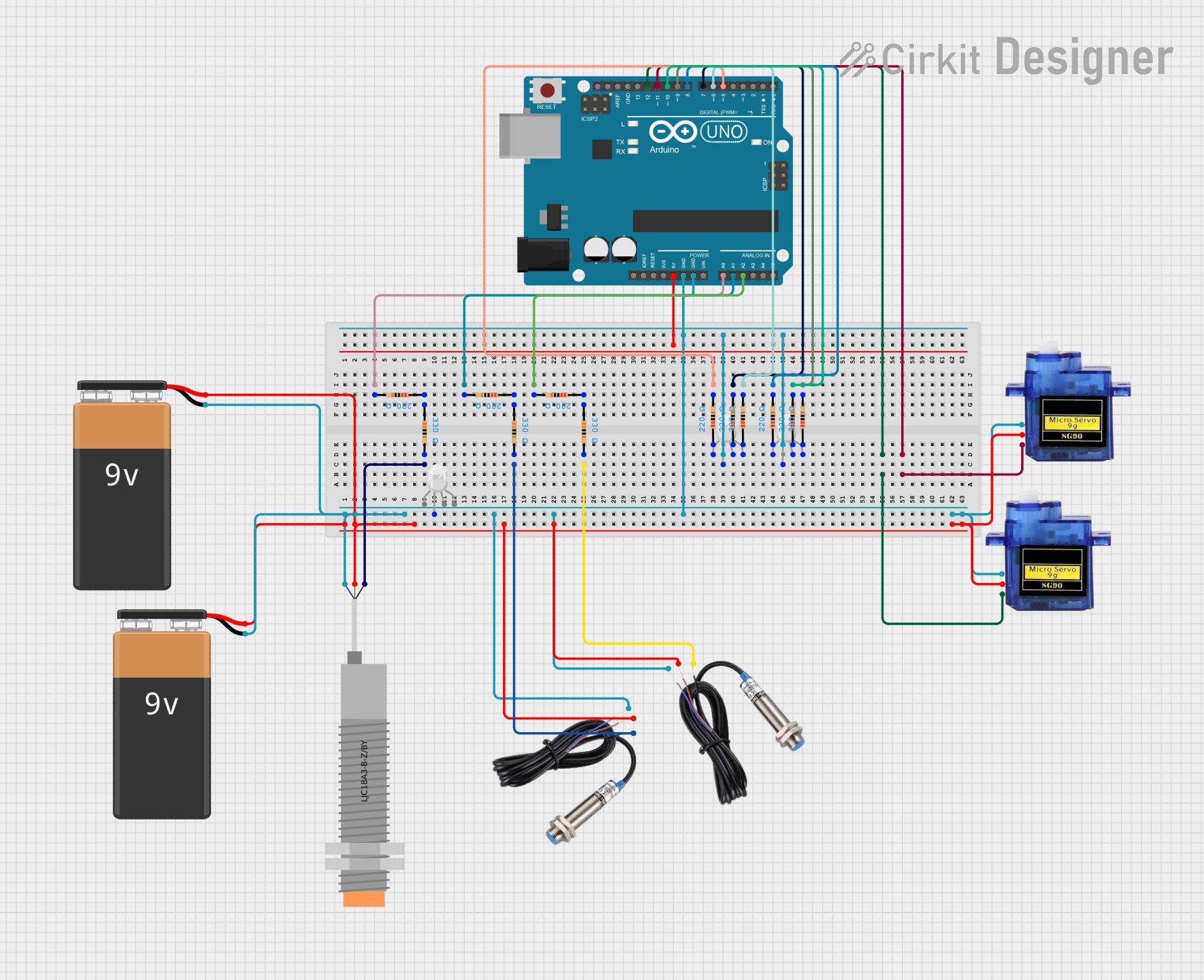
Circuit Documentation
Summary
This document provides a detailed overview of a circuit that includes various sensors, LEDs, resistors, a microcontroller (Arduino UNO), and power sources. The circuit is designed to interface with multiple sensors and actuators, providing a comprehensive setup for various applications.
Component List
LJC18A3-B-Z/BY Capacitive Proximity Sensor
- Pins: VO (BLU), VI (BRN), SIG (BLK)
- Description: Capacitive proximity sensor used to detect the presence of nearby objects without physical contact.
Inductive Sensor
- Pins: Signal, VCC, GND
- Description: Inductive sensor used to detect metallic objects.
9V Battery
- Pins: -, +
- Description: Power source for the circuit.
Micro servo 9G
- Pins: GND, +5V, PWM
- Description: Small servo motor used for precise control of angular position.
Arduino UNO
- Pins: UNUSED, IOREF, Reset, 3.3V, 5V, GND, Vin, A0, A1, A2, A3, A4, A5, SCL, SDA, AREF, D13, D12, D11, D10, D9, D8, D7, D6, D5, D4, D3, D2, D1, D0
- Description: Microcontroller board based on the ATmega328P.
Resistor
- Pins: pin1, pin2
- Description: Resistors with various resistance values used to limit current flow in the circuit.
- Properties:
- Resistance: 330 Ohms, 220 Ohms
RGB LED (Wokwi compatible)
- Pins: R, COM, G, B
- Description: RGB LED used to emit light in various colors.
Wiring Details
LJC18A3-B-Z/BY Capacitive Proximity Sensor
- SIG (BLK) connected to Resistor pin2
- VI (BRN) connected to 9V Battery +
- VO (BLU) connected to 9V Battery -
Inductive Sensor
- Signal connected to Resistor pin2
- VCC connected to 9V Battery +
- GND connected to 9V Battery -
9V Battery
- + connected to:
- LJC18A3-B-Z/BY Capacitive Proximity Sensor VI (BRN)
- Inductive Sensor VCC
- Micro servo 9G +5V
- - connected to:
- LJC18A3-B-Z/BY Capacitive Proximity Sensor VO (BLU)
- Inductive Sensor GND
- RGB LED (Wokwi compatible) COM
- Arduino UNO GND
- Micro servo 9G GND
Micro servo 9G
- PWM connected to Arduino UNO D11
- +5V connected to 9V Battery +
- GND connected to 9V Battery -
Arduino UNO
- A0 connected to Resistor pin2
- A1 connected to Resistor pin2
- A2 connected to Resistor pin2
- D5 connected to Resistor pin2
- D6 connected to Resistor pin2
- D7 connected to Resistor pin2
- D8 connected to Resistor pin2
- D9 connected to Resistor pin2
- D10 connected to Resistor pin2
- D11 connected to Micro servo 9G PWM
- D12 connected to Micro servo 9G PWM
- GND connected to:
- RGB LED (Wokwi compatible) COM
- 9V Battery -
Resistor
- pin1 connected to:
- Resistor pin1
- RGB LED (Wokwi compatible) R
- RGB LED (Wokwi compatible) G
- RGB LED (Wokwi compatible) B
- pin2 connected to:
- Arduino UNO A0
- Arduino UNO A1
- Arduino UNO A2
- Arduino UNO D5
- Arduino UNO D6
- Arduino UNO D7
- Arduino UNO D8
- Arduino UNO D9
- Arduino UNO D10
- LJC18A3-B-Z/BY Capacitive Proximity Sensor SIG (BLK)
- Inductive Sensor Signal
RGB LED (Wokwi compatible)
- COM connected to:
- RGB LED (Wokwi compatible) COM
- Arduino UNO GND
- R connected to Resistor pin1
- G connected to Resistor pin1
- B connected to Resistor pin1
Documented Code
Arduino UNO Code
void setup() {
  // put your setup code here, to run once:

}

void loop() {
  // put your main code here, to run repeatedly:

}
This concludes the documentation for the circuit. Each component and its connections have been detailed, along with the code used for the Arduino UNO microcontroller.