
ESP32-Based Weight Measurement System with LCD Display and Alert Buzzer
View and Edit Project In Cirkit Designer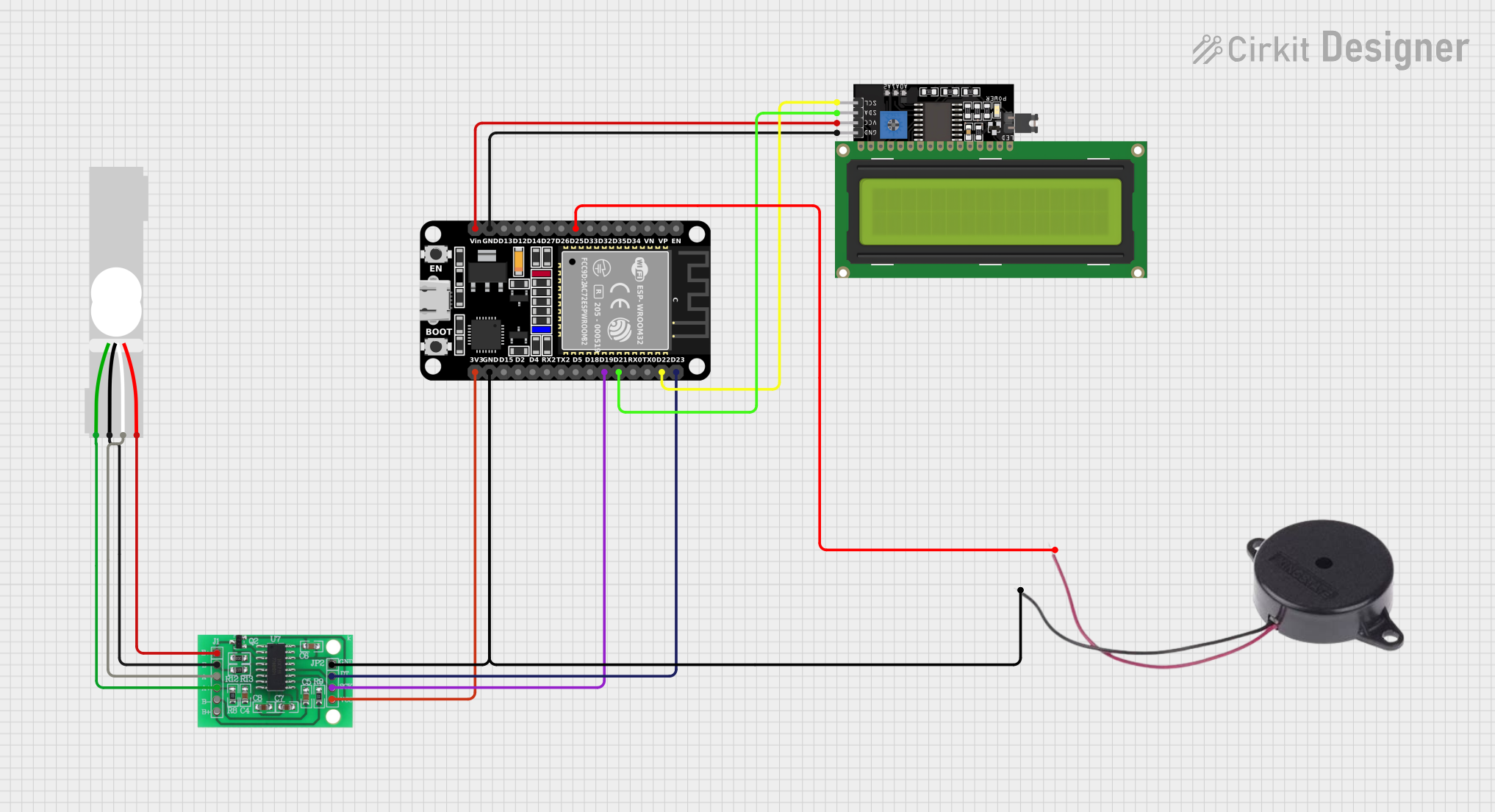
Circuit Documentation
Summary
This circuit integrates an ESP32 microcontroller with a load cell, an HX711 bridge sensor interface, an LCD display, and a buzzer. The ESP32 reads data from the load cell through the HX711 interface and displays the results on the LCD. It also controls the buzzer for audio feedback. The circuit is designed for applications such as digital weighing scales, where the load cell measures the weight, and the ESP32 processes and displays the information.
Component List
ESP32 (30 pin)
- Description: A microcontroller with Wi-Fi and Bluetooth capabilities, featuring a wide range of GPIO pins.
- Purpose: Acts as the central processing unit of the circuit, interfacing with the load cell, LCD display, and buzzer.
Load Cell - Red/white/black/green
- Description: A transducer that converts force into an electrical signal.
- Purpose: Measures the weight or force applied to it and sends the data to the HX711 for processing.
LCD Display 16x4 I2C
- Description: A 16x4 character LCD display with an I2C interface.
- Purpose: Displays the weight measurements and other information processed by the ESP32.
Buzzer
- Description: An electromechanical component that produces sound.
- Purpose: Provides audio feedback based on certain conditions or events detected by the ESP32.
HX711 - Bridge Sensor Interface
- Description: A precision 24-bit analog-to-digital converter (ADC) designed for weigh scales and industrial control applications to interface directly with a bridge sensor.
- Purpose: Amplifies and digitizes the analog signal from the load cell and sends it to the ESP32.
Wiring Details
ESP32 (30 pin)
- D25: Connected to the positive pin of the Buzzer.
- GND: Common ground shared with the LCD Display, Buzzer, and HX711.
- Vin: Connected to the VCC pin of the LCD Display.
- D23: Connected to the DATA (OUT) pin of the HX711.
- D22: Connected to the SCL pin of the LCD Display.
- D21: Connected to the SDA pin of the LCD Display.
- D19: Connected to the SCK - CLOCK (IN) pin of the HX711.
- 3V3: Supplies power to the 3.3/3.5V Supply pin of the HX711.
Load Cell - Red/white/black/green
- E+: Connected to the E+ pin of the HX711.
- A-: Connected to the A- pin of the HX711.
- E-: Connected to the E- pin of the HX711.
- A+: Connected to the A+ pin of the HX711.
LCD Display 16x4 I2C
- SCL: Connected to the D22 pin of the ESP32.
- SDA: Connected to the D21 pin of the ESP32.
- VCC: Connected to the Vin pin of the ESP32.
- GND: Shared ground with the ESP32.
Buzzer
- POSITIVE: Connected to the D25 pin of the ESP32.
- NEGATIVE: Shared ground with the ESP32.
HX711 - Bridge Sensor Interface
- E+: Connected to the E+ pin of the Load Cell.
- E-: Connected to the E- pin of the Load Cell.
- A-: Connected to the A- pin of the Load Cell.
- A+: Connected to the A+ pin of the Load Cell.
- GND - GROUND: Shared ground with the ESP32 and Buzzer.
- DATA (OUT): Connected to the D23 pin of the ESP32.
- SCK - CLOCK (IN): Connected to the D19 pin of the ESP32.
- 3.3/3.5V Supply: Powered by the 3V3 pin of the ESP32.
Documented Code
No code has been provided for the microcontroller. The documentation of the code would typically include a description of the functionality, setup and loop functions, and any libraries or external resources used. It would also cover the logic for reading sensor data, processing it, and outputting results to the display or buzzer. Since no code is available, this section cannot be completed.