Arduino UNO Controlled RGB LED Light Show
Circuit Documentation
Summary of the Circuit
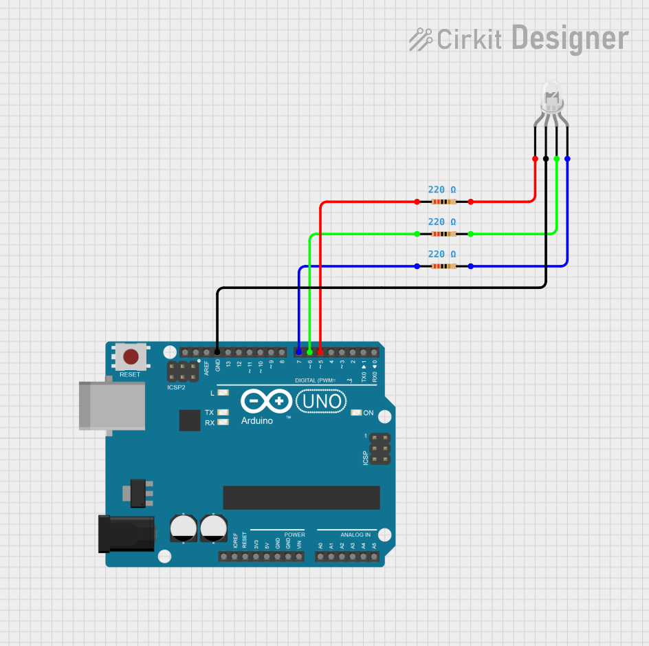
This circuit is designed to control a common cathode RGB LED using an Arduino UNO microcontroller. The LED's red, green, and blue anodes are connected through 220 Ohm resistors to the digital pins D5, D6, and D7 of the Arduino, respectively. The common cathode of the LED is connected to the ground (GND) of the Arduino. The Arduino is programmed to cycle through various colors by adjusting the intensity of each color channel.
Component List
LED: Four Pin (Common Cathode)
- Description: A four-pin RGB LED with a common cathode.
- Pins: red anode, common cathode, green anode, blue anode
- Purpose: To display various colors by adjusting the intensity of the red, green, and blue anodes.
Arduino UNO
- Description: A microcontroller board based on the ATmega328P.
- Pins: UNUSED, IOREF, Reset, 3.3V, 5V, GND, Vin, A0-A5, SCL, SDA, AREF, D0-D13
- Purpose: To control the RGB LED by providing logic signals to the anodes through resistors.
Resistor (220 Ohms)
- Description: A resistor with a resistance of 220 Ohms.
- Pins: pin1, pin2
- Purpose: To limit the current flowing through the LED anodes, preventing damage to the LED.
Wiring Details
LED: Four Pin (Common Cathode)
- Red Anode: Connected to pin2 of a 220 Ohm resistor.
- Common Cathode: Connected to the GND pin on the Arduino UNO.
- Green Anode: Connected to pin2 of a 220 Ohm resistor.
- Blue Anode: Connected to pin2 of a 220 Ohm resistor.
Arduino UNO
- GND: Connected to the common cathode of the RGB LED.
- D5: Connected to pin1 of a 220 Ohm resistor leading to the red anode of the RGB LED.
- D6: Connected to pin1 of a 220 Ohm resistor leading to the green anode of the RGB LED.
- D7: Connected to pin1 of a 220 Ohm resistor leading to the blue anode of the RGB LED.
Resistor (220 Ohms)
- Resistor for Red Anode:
- pin1: Connected to D5 on the Arduino UNO.
- pin2: Connected to the red anode of the RGB LED.
- Resistor for Green Anode:
- pin1: Connected to D6 on the Arduino UNO.
- pin2: Connected to the green anode of the RGB LED.
- Resistor for Blue Anode:
- pin1: Connected to D7 on the Arduino UNO.
- pin2: Connected to the blue anode of the RGB LED.
Documented Code
/*
 * RGB LED Control with Arduino
 * This sketch controls a common cathode RGB LED connected to an Arduino UNO.
 * It cycles through different colors by setting the intensity of each color channel.
 * The LED is connected through 220 Ohm resistors on pins D5, D6, and D7 for red, green, and blue anodes respectively.
 */

// Defining variables for the GPIO pins on Arduino
int redPin = 5;    // Red LED anode connected to D5 through a resistor
int greenPin = 6;  // Green LED anode connected to D6 through a resistor
int bluePin = 7;   // Blue LED anode connected to D7 through a resistor

void setup() {
  // Defining the pins as OUTPUT
  pinMode(redPin, OUTPUT);
  pinMode(greenPin, OUTPUT);
  pinMode(bluePin, OUTPUT);
}

void loop() {
  setColor(255, 0, 0); // Red Color
  delay(1000);
  setColor(0, 255, 0); // Green Color
  delay(1000);
  setColor(0, 0, 255); // Blue Color
  delay(1000);
  setColor(255, 255, 255); // White Color
  delay(1000);
  setColor(170, 0, 255); // Purple Color
  delay(1000);
  setColor(127, 127, 127); // Light Blue
  delay(1000);
}

void setColor(int redValue, int greenValue, int blueValue) {
  // The common cathode RGB LED requires a common GND and the anodes to be driven high.
  // Since the LED is common cathode, we need to reverse the logic of the analogWrite values.
  analogWrite(redPin, 255 - redValue);
  analogWrite(greenPin, 255 - greenValue);
  analogWrite(bluePin, 255 - blueValue);
}
The code provided is an Arduino sketch that defines the pin connections for the RGB LED and includes a function setColor to change the color of the LED. The loop function cycles through various colors with a one-second delay between each color change. The analogWrite function is used to set the intensity of each color channel, with the values inverted due to the common cathode configuration of the LED.