
Circuit Documentation
Summary
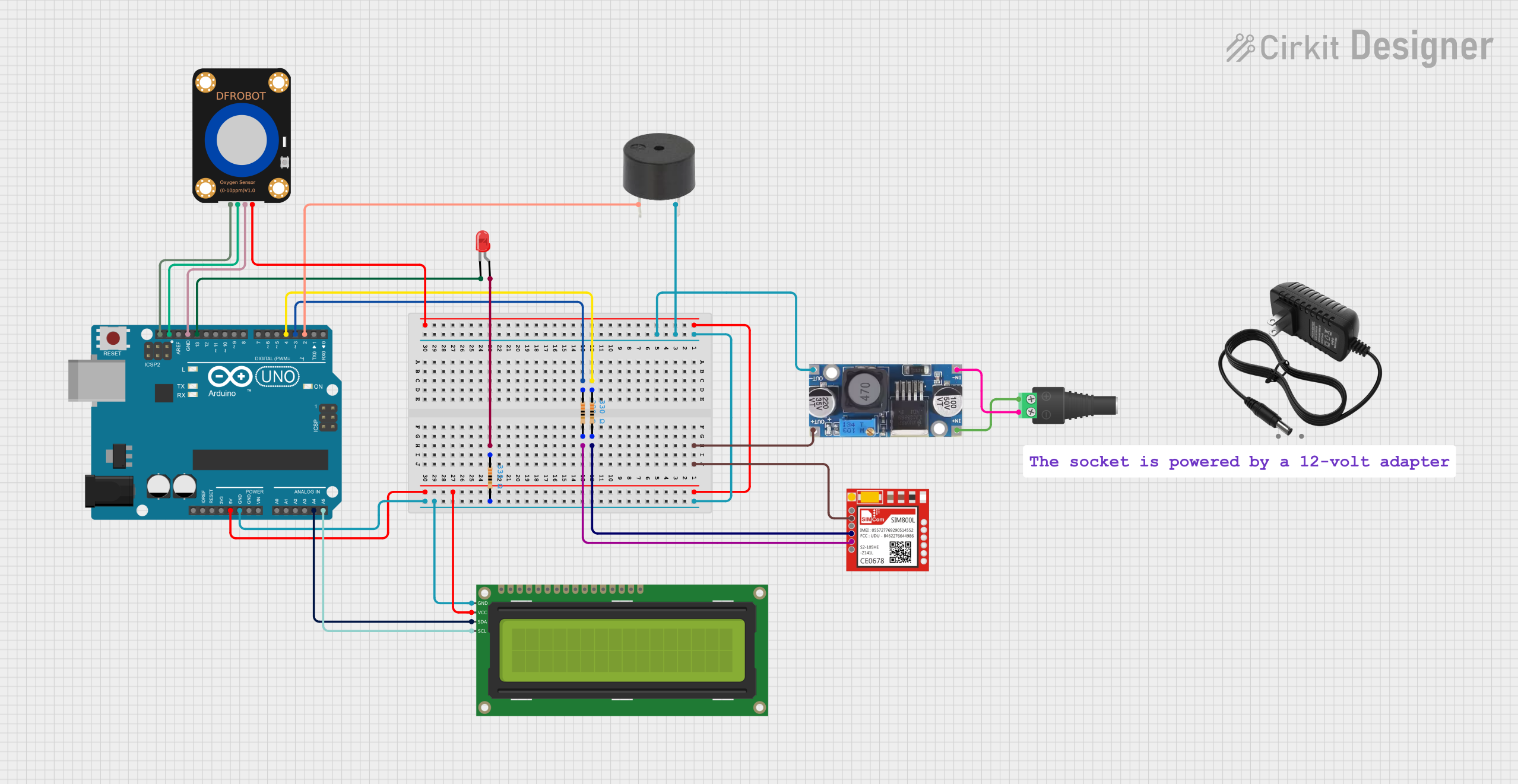
This circuit is designed to monitor oxygen levels using a DFRobot Oxygen Sensor and display the readings on a 16x2 I2C LCD. It also includes an alarm system with a buzzer and an LED that activates when oxygen levels fall below a certain threshold. The system is powered by a 12V power supply, which is stepped down using a Buck converter. An Arduino UNO microcontroller is used to control the entire system, and a SIM800L module is included for sending SMS alerts when oxygen levels are low.
Component List
Arduino UNO
- Description: Microcontroller board based on the ATmega328P.
- Pins: UNUSED, IOREF, Reset, 3.3V, 5V, GND, Vin, A0, A1, A2, A3, A4, A5, SCL, SDA, AREF, D13, D12, D11, D10, D9, D8, D7, D6, D5, D4, D3, D2, D1, D0
LED: Two Pin (red)
- Description: Red LED with two pins.
- Pins: cathode, anode
Resistor (330 Ohms)
- Description: Resistor with a resistance of 330 Ohms.
- Pins: pin1, pin2
Buzzer
- Description: Buzzer for sound alarm.
- Pins: PIN, GND
DFRobot Oxygen Sensor
- Description: Sensor for measuring oxygen levels.
- Pins: Pin 1, Pin 2, Pin 3, Pin 4
16x2 I2C LCD
- Description: 16x2 character LCD with I2C interface.
- Pins: GND, VCC, SDA, SCL
2.1mm Barrel Jack with Terminal Block
- Description: Power connector for 12V power supply.
- Pins: POS, NEG
Step down Buck converter
- Description: Converts 12V to 5V.
- Pins: IN +, IN - GND, OUT +, OUT - GND
12V power supply
- Description: Provides 12V power to the circuit.
- Pins: +, -
SIM800L
- Description: GSM/GPRS module for sending SMS.
- Pins: NET, RST, VCC, RXD, TXD, GND
Wiring Details
Arduino UNO
- D2: Connected to PIN of the Buzzer
- D3: Connected to pin1 of a Resistor (330 Ohms)
- D4: Connected to pin1 of another Resistor (330 Ohms)
- D13: Connected to cathode of the LED
- A4: Connected to SDA of the 16x2 I2C LCD
- A5: Connected to SCL of the 16x2 I2C LCD
- 5V: Connected to VCC of the 16x2 I2C LCD and Pin 4 of the DFRobot Oxygen Sensor
- GND: Connected to GND of the Buzzer, OUT - GND of the Step down Buck converter, GND of the 16x2 I2C LCD, and Pin 3 of the DFRobot Oxygen Sensor
- SCL: Connected to Pin 1 of the DFRobot Oxygen Sensor
- SDA: Connected to Pin 2 of the DFRobot Oxygen Sensor
LED: Two Pin (red)
- anode: Connected to pin1 of a Resistor (330 Ohms)
- cathode: Connected to D13 of the Arduino UNO
Resistor (330 Ohms)
- pin1: Connected to D3 of the Arduino UNO
- pin2: Connected to TXD of the SIM800L
Resistor (330 Ohms)
- pin1: Connected to D4 of the Arduino UNO
- pin2: Connected to RXD of the SIM800L
Resistor (330 Ohms)
- pin1: Connected to anode of the LED
- pin2: Connected to GND of the Buzzer
Buzzer
- PIN: Connected to D2 of the Arduino UNO
- GND: Connected to GND of the Arduino UNO
DFRobot Oxygen Sensor
- Pin 1: Connected to SCL of the Arduino UNO
- Pin 2: Connected to SDA of the Arduino UNO
- Pin 3: Connected to GND of the Arduino UNO
- Pin 4: Connected to 5V of the Arduino UNO
16x2 I2C LCD
- GND: Connected to GND of the Arduino UNO
- VCC: Connected to 5V of the Arduino UNO
- SDA: Connected to A4 of the Arduino UNO
- SCL: Connected to A5 of the Arduino UNO
2.1mm Barrel Jack with Terminal Block
- POS: Connected to IN + of the Step down Buck converter
- NEG: Connected to IN - GND of the Step down Buck converter
Step down Buck converter
- IN +: Connected to POS of the 2.1mm Barrel Jack with Terminal Block
- IN - GND: Connected to NEG of the 2.1mm Barrel Jack with Terminal Block
- OUT +: Connected to VCC of the SIM800L
- OUT - GND: Connected to GND of the Arduino UNO
12V power supply
- +: Connected to POS of the 2.1mm Barrel Jack with Terminal Block
- -: Connected to NEG of the 2.1mm Barrel Jack with Terminal Block
SIM800L
- VCC: Connected to OUT + of the Step down Buck converter
- RXD: Connected to pin2 of a Resistor (330 Ohms)
- TXD: Connected to pin2 of another Resistor (330 Ohms)
- GND: Connected to GND of the Arduino UNO
Documented Code
Arduino UNO Code
#include <SoftwareSerial.h>
#include "DFRobot_OxygenSensor.h"
#include "LiquidCrystal_I2C.h"

//Create software serial object to communicate with SIM800L
SoftwareSerial mySerial(4, 3);  //SIM800L Tx & Rx is connected to Arduino #3 & #2

LiquidCrystal_I2C lcd(0x27, 16, 2);
#define Oxygen_IICAddress ADDRESS_3
#define COLLECT_NUMBER 10  // collect number, the collection range is 1-100.
DFRobot_OxygenSensor oxygen;
bool flag=0;
void setup(void) {

  lcd.init();
  lcd.backlight();
  lcd.setCursor(0, 0);
  lcd.print("Welcome");
  pinMode(2, OUTPUT);
  pinMode(13, OUTPUT);
  Serial.begin(9600);
  while (!oxygen.begin(Oxygen_IICAddress)) {
    Serial.println("I2c device number error !");
    delay(1000);
  }
  Serial.println("I2c connect success !");
  //Begin serial communication with Arduino and Arduino IDE (Serial Monitor)
  Serial.begin(9600);

  //Begin serial communication with Arduino and SIM800L
  mySerial.begin(9600);

  Serial.println("Initializing...");
  delay(1000);

  mySerial.println("AT");  //Once the handshake test is successful, it will back to OK
  updateSerial();
}

void loop(void) {

  updateSerial();
  float oxygenData = oxygen.getOxygenData(COLLECT_NUMBER);
  //Serial.print(" oxygen concentration is ");
  //Serial.print(oxygenData);
  //Serial.println(" %vol");
  lcd.clear();
  lcd.setCursor(0, 0);
  lcd.print("Oxygen conc. is ");

  if (oxygenData < 18.99) {
    digitalWrite(2, HIGH);   //sound alarm on
    digitalWrite(13, HIGH);  //light alarm on
    lcd.setCursor(0, 1);
    lcd.print(oxygenData);
    lcd.println(" %vol| LOW ");
    if(flag ==0){
    mySerial.println("AT+CMGF=1");  // Configuring TEXT mode
    updateSerial();
    mySerial.println("AT+CMGS=\"+966557143252\"");  //change ZZ with country code and xxxxxxxxxxx with phone number to sms
    updateSerial();
    mySerial.print("Oxygen Level is low");  //text content
    updateSerial();
    mySerial.write(26