Cirkit Designer
Your all-in-one circuit design IDE
Home /
Project Documentation
Arduino UNO-Based Smart Helmet with Alcohol Detection and Emergency Alert System
Circuit Documentation
Summary
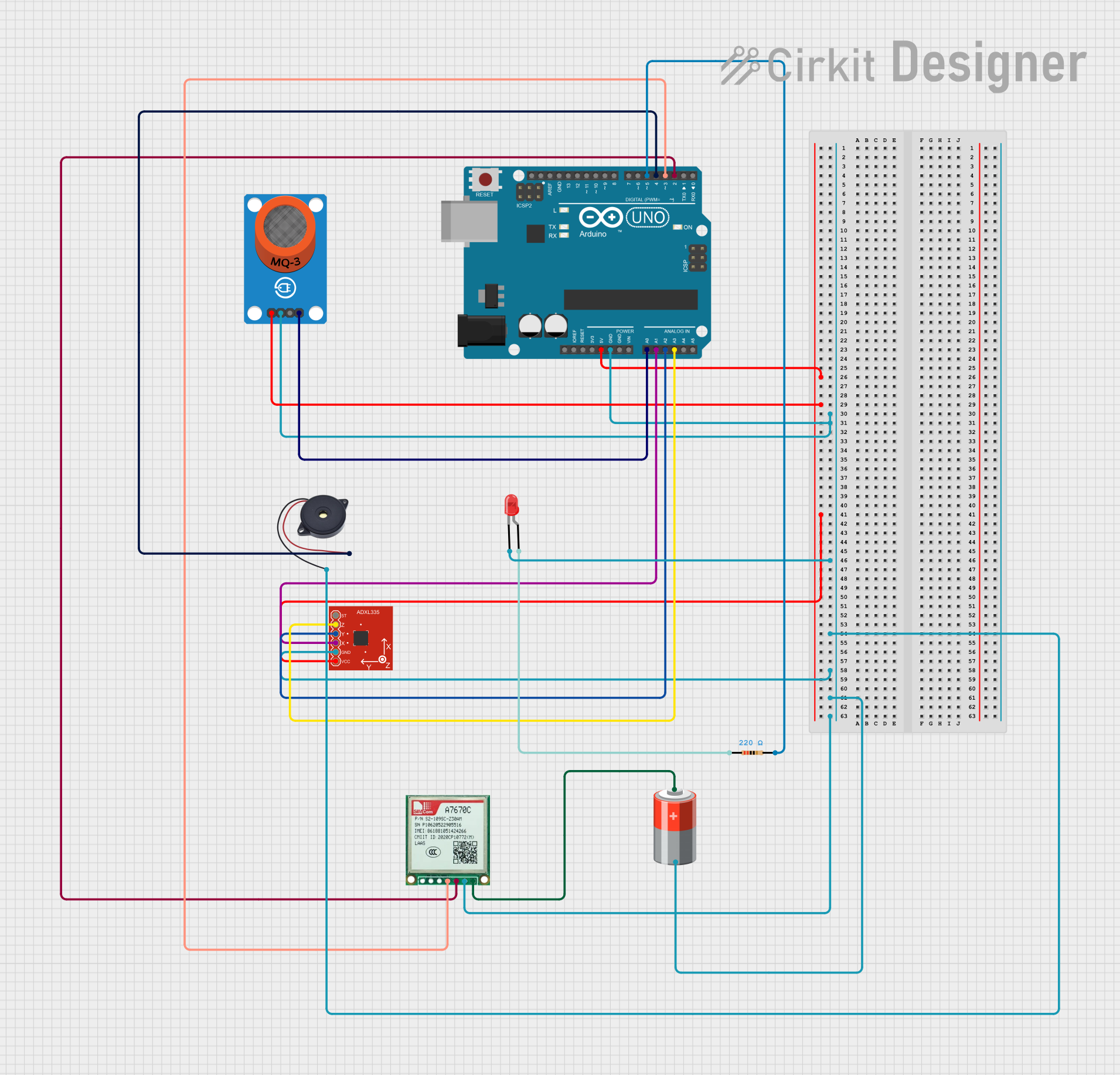
This document provides a detailed overview of a Safe Track Helmet System circuit. The system includes an Arduino UNO microcontroller, an MQ-3 alcohol sensor, a Triple Axis Accelerometer (ADXL335), a red LED, a Sim A7670c GSM module, a 5V battery, a resistor, and a buzzer. The system is designed to detect alcohol levels and sudden impacts, and it can send an SOS message in case of an emergency.
Component List
Arduino UNO
- Description: Microcontroller board based on the ATmega328P.
- Pins: UNUSED, IOREF, Reset, 3.3V, 5V, GND, Vin, A0, A1, A2, A3, A4, A5, SCL, SDA, AREF, D13, D12, D11, D10, D9, D8, D7, D6, D5, D4, D3, D2, D1, D0
MQ-3 Breakout
- Description: Alcohol sensor module.
- Pins: VCC, GND, DO, AO
Triple Axis Accelerometer (ADXL335)
- Description: Accelerometer module for measuring acceleration in three axes.
- Pins: ST, ZOUT, YOUT, XOUT, GND, VCC
LED: Two Pin (red)
- Description: Red LED for visual indication.
- Pins: cathode, anode
Sim A7670c
- Description: GSM module for sending SMS.
- Pins: Vin, Gnd, Tx, Rx
5V Battery
- Description: Power source for the circuit.
- Pins: +, -
Resistor
- Description: 220 Ohms resistor.
- Pins: pin1, pin2
- Properties: Resistance: 220 Ohms
Buzzer
- Description: Buzzer for audio indication.
- Pins: GND, IN
Wiring Details
Arduino UNO
- 5V connected to VCC of MQ-3 Breakout and VCC of Triple Axis Accelerometer (ADXL335)
- GND connected to GND of MQ-3 Breakout, cathode of LED, GND of Buzzer, GND of Triple Axis Accelerometer (ADXL335), - of 5V Battery, and Gnd of Sim A7670c
- A0 connected to AO of MQ-3 Breakout
- A1 connected to XOUT of Triple Axis Accelerometer (ADXL335)
- A2 connected to YOUT of Triple Axis Accelerometer (ADXL335)
- A3 connected to ZOUT of Triple Axis Accelerometer (ADXL335)
- D5 connected to pin2 of Resistor
- D4 connected to IN of Buzzer
- D3 connected to Rx of Sim A7670c
- D2 connected to Tx of Sim A7670c
MQ-3 Breakout
- VCC connected to 5V of Arduino UNO
- GND connected to GND of Arduino UNO
- AO connected to A0 of Arduino UNO
Triple Axis Accelerometer (ADXL335)
- VCC connected to 5V of Arduino UNO
- GND connected to GND of Arduino UNO
- XOUT connected to A1 of Arduino UNO
- YOUT connected to A2 of Arduino UNO
- ZOUT connected to A3 of Arduino UNO
LED: Two Pin (red)
- cathode connected to GND of Arduino UNO
- anode connected to pin1 of Resistor
Sim A7670c
- Vin connected to + of 5V Battery
- Gnd connected to GND of Arduino UNO
- Tx connected to D2 of Arduino UNO
- Rx connected to D3 of Arduino UNO
5V Battery
- + connected to Vin of Sim A7670c
- - connected to GND of Arduino UNO
Resistor
- pin1 connected to anode of LED
- pin2 connected to D5 of Arduino UNO
Buzzer
- GND connected to GND of Arduino UNO
- IN connected to D4 of Arduino UNO
Documented Code
#include <SoftwareSerial.h>

// Pin Definitions
#define MQ3_PIN A0           // Alcohol sensor pin
#define BUZZER_PIN 4         // Buzzer pin
#define LED_PIN 5            // Red LED pin
#define XOUT_PIN A1          // X-axis of accelerometer
#define YOUT_PIN A2          // Y-axis of accelerometer
#define ZOUT_PIN A3          // Z-axis of accelerometer

// GSM Module Configuration
SoftwareSerial gsm(2, 3);    // GSM module TX (D2), RX (D3 via voltage divider)

void setup() {
  // Initialize pins
  pinMode(MQ3_PIN, INPUT);
  pinMode(BUZZER_PIN, OUTPUT);
  pinMode(LED_PIN, OUTPUT);
  pinMode(XOUT_PIN, INPUT);
  pinMode(YOUT_PIN, INPUT);
  pinMode(ZOUT_PIN, INPUT);

  // Initialize Serial Monitor
  Serial.begin(9600);
  // Initialize GSM Module
  gsm.begin(9600);
  delay(2000);

  Serial.println("Safe Track Helmet System Initialized");
}

void loop() {
  checkAlcohol();
  checkEmergency();
  delay(500);  // Adjust delay as needed
}

void checkAlcohol() {
  int alcoholLevel = analogRead(MQ3_PIN); // Read alcohol sensor value
  Serial.print("Alcohol Level: ");
  Serial.println(alcoholLevel);

  // Threshold for alcohol detection
  if (alcoholLevel > 500) {
    Serial.println("Alcohol detected! Activating buzzer...");
    digitalWrite(BUZZER_PIN, HIGH); // Activate buzzer
    delay(1000);
    digitalWrite(BUZZER_PIN, LOW);
    delay(1000);
  } else {
    digitalWrite(BUZZER_PIN, LOW); // Turn off buzzer
  }
}

void checkEmergency() {
  // Read accelerometer values
  int x = analogRead(XOUT_PIN);
  int y = analogRead(YOUT_PIN);
  int z = analogRead(ZOUT_PIN);

  Serial.print("X: "); Serial.print(x);
  Serial.print(" Y: "); Serial.print(y);
  Serial.print(" Z: "); Serial.println(z);

  // Threshold for detecting sudden impact or tilt
  if (x > 600 || y > 600 || z < 400) {
    Serial.println("Emergency detected! Sending SOS...");
    sendSOS();
    blinkLED();
  }
}

void sendSOS() {
  gsm.println("AT+CMGF=1"); // Set GSM to Text Mode
  delay(1000);
  gsm.println("AT+CMGS=\"+1234567890\""); // Replace with the emergency contact number
  delay(1000);
  gsm.print("Emergency! The rider has met with an accident. Please help.");
  delay(1000);
  gsm.write(26); // ASCII code for CTRL+Z to send SMS
  delay(5000);
}

void blinkLED() {
  for (int i = 0; i < 10; i++) { // Blink the LED for better visibility
    digitalWrite(LED_PIN, HIGH);
    delay(500);
    digitalWrite(LED_PIN, LOW);
    delay(500);
  }
}
This code initializes the Safe Track Helmet System, reads sensor values, and performs actions based on the readings. The system can detect alcohol levels and sudden impacts, and it sends an SOS message in case of an emergency.