
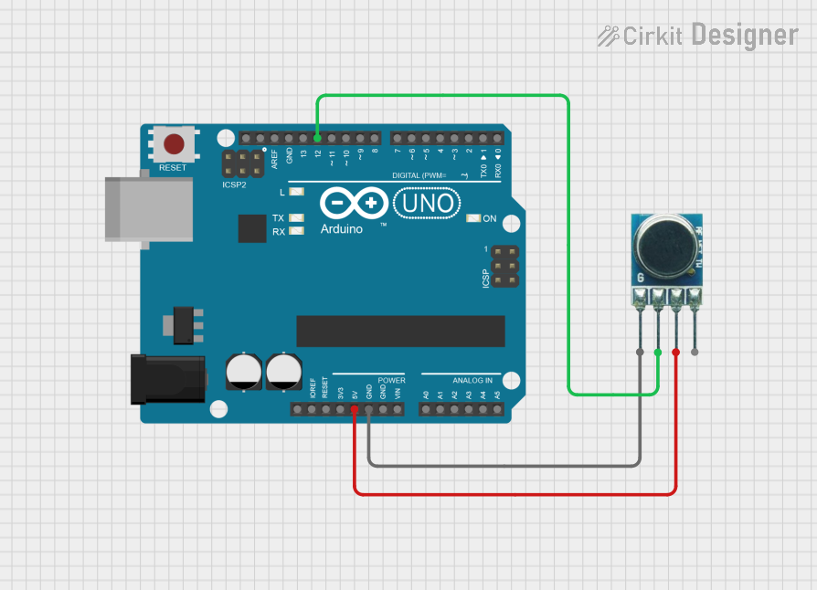
Circuit Documentation
Summary
This circuit integrates an Arduino UNO microcontroller with a 433MHz RF Transmitter module. The Arduino UNO serves as the central processing unit, controlling the data transmission through the RF module. The RF Transmitter is used to send data wirelessly at a frequency of 433MHz. The circuit is powered by the 5V output from the Arduino, and the ground is shared between both components to complete the circuit.
Component List
Arduino UNO
- Description: A microcontroller board based on the ATmega328P.
- Pins: UNUSED, IOREF, Reset, 3.3V, 5V, GND, Vin, A0-A5, SCL, SDA, AREF, D0-D13
- Purpose: Acts as the central processing unit for controlling the RF Transmitter and managing data transmission.
433MHz RF Transmitter
- Description: A wireless transmitter module for sending data at 433MHz.
- Pins: GND, Data In, VCC, ANT
- Purpose: Transmits data wirelessly when controlled by the Arduino UNO.
Wiring Details
Arduino UNO
- 5V connected to 433MHz RF Transmitter VCC
- GND connected to 433MHz RF Transmitter GND
- D12 connected to 433MHz RF Transmitter Data In
433MHz RF Transmitter
- VCC connected to Arduino UNO 5V
- GND connected to Arduino UNO GND
- Data In connected to Arduino UNO D12
- ANT (Antenna) - No connection specified
Documented Code
Arduino UNO Code (sketch.ino)
void setup() {
  // put your setup code here, to run once:

}

void loop() {
  // put your main code here, to run repeatedly:

}
Note: The provided code is a template and does not contain any specific functionality. It is expected that the user will add the necessary code to control the 433MHz RF Transmitter and handle data transmission.
Additional Files
- documentation.txt: This file is mentioned but no content is provided. It is likely intended for additional notes or manual documentation by the user.