Cirkit Designer
Your all-in-one circuit design IDE
Home /
Project Documentation
Arduino UNO Controlled LED Blinker
Circuit Documentation
Summary of the Circuit
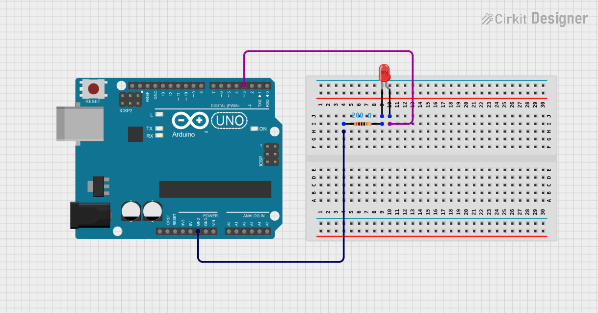
This circuit consists of an Arduino UNO microcontroller, a red two-pin LED, and a resistor. The purpose of the circuit is to control the LED using one of the digital pins (D3) on the Arduino UNO. The resistor is used to limit the current flowing through the LED to prevent damage.
Component List
Arduino UNO
- Description: A microcontroller board based on the ATmega328P.
- Pins Used: GND, D3
- Purpose: Acts as the control unit for the LED.
LED: Two Pin (red)
- Description: A basic red light-emitting diode.
- Pins: cathode, anode
- Purpose: Emits light when powered.
Resistor
- Description: A passive two-terminal electrical component that implements electrical resistance as a circuit element.
- Resistance: 200 Ohms
- Purpose: Limits the current flowing through the LED.
Wiring Details
Arduino UNO
- GND is connected to one pin of the Resistor.
- D3 is connected to the anode of the LED.
LED: Two Pin (red)
- Anode is connected to the D3 pin of the Arduino UNO.
- Cathode is connected to one pin of the Resistor.
Resistor
- One pin is connected to the GND pin of the Arduino UNO.
- The other pin is connected to the cathode of the LED.
Documented Code
Arduino UNO Code (sketch.ino)
void setup() {
  // put your setup code here, to run once:

}

void loop() {
  // put your main code here, to run repeatedly:

}
Additional Notes
- The provided code is a template and does not contain any functionality. To control the LED, code needs to be added to the
setup()function to initialize pin D3 as an output, and to theloop()function to turn the LED on and off. - The
documentation.txtfile is empty and does not contain any additional information about the code or circuit.