Cirkit Designer
Your all-in-one circuit design IDE
Home /
Project Documentation
Arduino UNO-Based Wi-Fi Controlled Servo and Ultrasonic Sensor System
Circuit Documentation
Summary
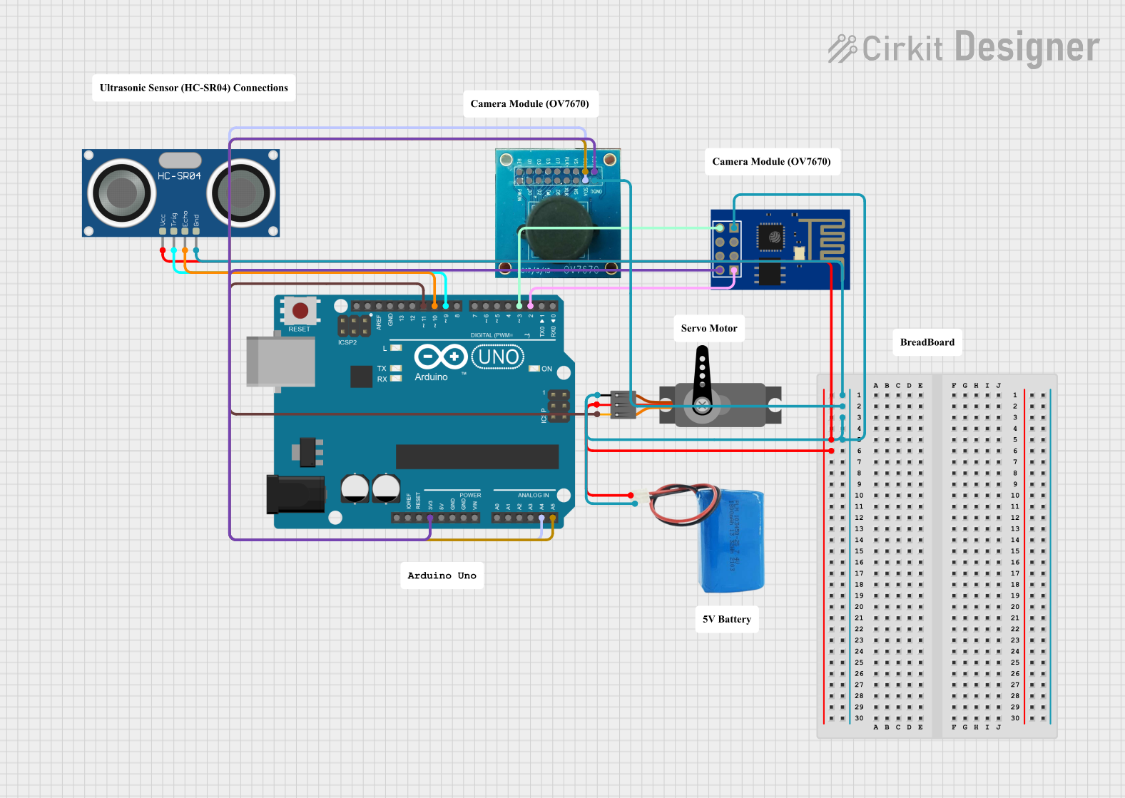
This circuit involves an Arduino UNO microcontroller interfacing with a Servo motor, an HC-SR04 Ultrasonic Sensor, an OV7670 camera module, and an ESP8266 ESP-01 WiFi module. The circuit is powered by a 5V battery. The Arduino UNO controls the Servo motor and reads data from the Ultrasonic Sensor and the camera module. The WiFi module is used for wireless communication.
Component List
Servo
- Pins: GND, VCC, PWM
- Description: A motor that can be controlled to move to a specific position.
- Purpose in Circuit: Used for precise control of mechanical movement.
Arduino UNO
- Pins: UNUSED, IOREF, Reset, 3.3V, 5V, GND, Vin, A0, A1, A2, A3, A4, A5, SCL, SDA, AREF, D13, D12, D11, D10, D9, D8, D7, D6, D5, D4, D3, D2, D1, D0
- Description: A microcontroller board based on the ATmega328P.
- Purpose in Circuit: Acts as the main controller for the circuit.
5V Battery
- Pins: positive, negative
- Description: A power source providing 5V.
- Purpose in Circuit: Supplies power to the circuit components.
HC-SR04 Ultrasonic Sensor
- Pins: VCC, TRIG, ECHO, GND
- Description: A sensor used to measure distance by using ultrasonic waves.
- Purpose in Circuit: Measures distance to objects.
OV7670 Camera Module
- Pins: RET, PWDN, D1, D0, D3, D2, D4, D5, D6, PLK, XLK, D7, VS, HS, SCL, SDA, 3.3V, DGND
- Description: A camera module used for capturing images.
- Purpose in Circuit: Captures images for processing.
ESP8266 ESP-01 WiFi Module
- Pins: TXD, CH_PD, RST, VCC, GND, GPIO_2, GPIO_0, RXD
- Description: A WiFi module used for wireless communication.
- Purpose in Circuit: Provides wireless communication capabilities.
Wiring Details
Servo
- GND connected to 5V Battery negative terminal.
- VCC connected to 5V Battery positive terminal.
- PWM connected to Arduino UNO D11.
Arduino UNO
- 3.3V connected to OV7670 3.3V and ESP8266 ESP-01 WiFi Module VCC.
- A4 connected to OV7670 SDA.
- A5 connected to OV7670 SCL.
- D11 connected to Servo PWM.
- D10 connected to HC-SR04 Ultrasonic Sensor ECHO.
- D9 connected to HC-SR04 Ultrasonic Sensor TRIG.
- D3 connected to ESP8266 ESP-01 WiFi Module TXD.
- D2 connected to ESP8266 ESP-01 WiFi Module RXD.
5V Battery
- negative connected to Servo GND, HC-SR04 Ultrasonic Sensor GND, OV7670 DGND, and ESP8266 ESP-01 WiFi Module GND.
- positive connected to Servo VCC and HC-SR04 Ultrasonic Sensor VCC.
HC-SR04 Ultrasonic Sensor
- GND connected to 5V Battery negative terminal.
- VCC connected to 5V Battery positive terminal.
- TRIG connected to Arduino UNO D9.
- ECHO connected to Arduino UNO D10.
OV7670 Camera Module
- DGND connected to 5V Battery negative terminal.
- 3.3V connected to Arduino UNO 3.3V.
- SDA connected to Arduino UNO A4.
- SCL connected to Arduino UNO A5.
ESP8266 ESP-01 WiFi Module
- GND connected to 5V Battery negative terminal.
- VCC connected to Arduino UNO 3.3V.
- TXD connected to Arduino UNO D3.
- RXD connected to Arduino UNO D2.
Documented Code
Arduino UNO Code (sketch.ino)
void setup() {
  // put your setup code here, to run once:

}

void loop() {
  // put your main code here, to run repeatedly:

}
Additional Documentation (documentation.txt)
This documentation provides a comprehensive overview of the circuit, including a summary, detailed component list, wiring details, and the code used in the microcontroller.