
ESP32-Based Smart Motor Control and LED Matrix Display with Microphone Input
View and Edit Project In Cirkit Designer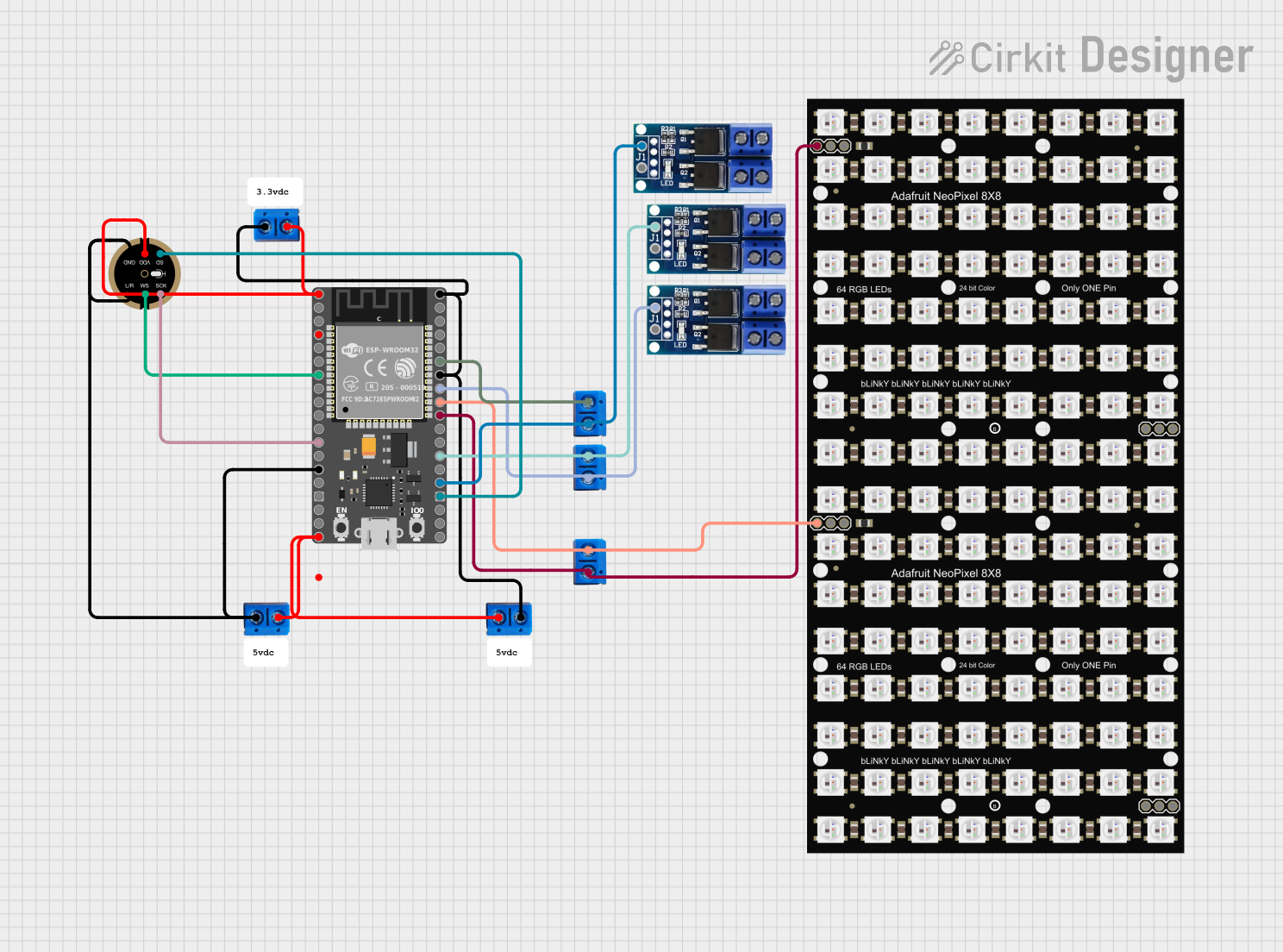
Circuit Documentation
Summary
This circuit design involves two HiLetGo ESP-32 microcontrollers, an INMP441 microphone, several Terminal PCB 2 Pin connectors, Motor Driver - N-Mos PWM Triggers, and Adafruit NeoPixel NeoMatrix 8x8 displays. The ESP-32 microcontrollers are used to control various components, including the microphone, motor drivers, and NeoPixel displays. The Terminal PCB 2 Pin connectors are used for power distribution and signal routing.
Component List
HiLetGo ESP-32
- Description: A powerful microcontroller with Wi-Fi and Bluetooth capabilities.
- Pins: 3.3, EN, GPIO36, GPIO39, GPIO34, GPIO35, GPIO32, GPIO33, GPIO25, GPIO26, GPIO27, GPIO14, GPIO12, GND, GPIO13, GPIO9, GPIO10, GPIO11, VIN, GPIO6, GPIO7, GPIO8, GPIO15, GPIO2, GPIO0, GPIO4, GPIO16, GPIO17, GPIO5, GPIO18, GPIO19, GPIO21, GPIO3, GPIO1, GPIO22, GPIO23
Terminal PCB 2 Pin
- Description: A simple 2-pin terminal block for easy connection and disconnection of wires.
- Pins: Pin A, Pin B
INMP441 FRONT MIC
- Description: A high-performance, low-power, digital-output omnidirectional MEMS microphone.
- Pins: L/R, WS, SCK, SD, VDD, GND
Motor Driver - N-Mos PWM Trigger
- Description: A motor driver module that uses N-MOSFETs for PWM control.
- Pins: + PWM, GND, OUT -, OUT +, DC OUT +, DC IN -
Adafruit NeoPixel NeoMatrix 8x8
- Description: An 8x8 matrix of individually addressable RGB LEDs.
- Pins: IN, VDD, GND, OUT
Wiring Details
HiLetGo ESP-32 (1)
- 3.3V: Connected to Pin B of Terminal PCB 2 Pin, VDD of INMP441 FRONT MIC
- GND: Connected to Pin B of Terminal PCB 2 Pin, L/R and GND of INMP441 FRONT MIC
- VIN: Connected to Pin A of Terminal PCB 2 Pin
- GPIO32: Connected to WS of INMP441 FRONT MIC
- GPIO14: Connected to SCK of INMP441 FRONT MIC
- GPIO15: Connected to SD of INMP441 FRONT MIC
- GPIO2: Connected to + PWM of Motor Driver - N-Mos PWM Trigger, Pin B of Terminal PCB 2 Pin
- GPIO4: Connected to + PWM of Motor Driver - N-Mos PWM Trigger, Pin A of Terminal PCB 2 Pin
- GPIO5: Connected to IN of Adafruit NeoPixel NeoMatrix 8x8, Pin B of Terminal PCB 2 Pin
- GPIO18: Connected to IN of Adafruit NeoPixel NeoMatrix 8x8, Pin A of Terminal PCB 2 Pin
- GPIO19: Connected to + PWM of Motor Driver - N-Mos PWM Trigger, Pin B of Terminal PCB 2 Pin
- GPIO21: Connected to Pin A of Terminal PCB 2 Pin
HiLetGo ESP-32 (2)
- 3.3V: Connected to Pin B of Terminal PCB 2 Pin, VDD of INMP441 FRONT MIC
- GND: Connected to Pin B of Terminal PCB 2 Pin, L/R and GND of INMP441 FRONT MIC
- VIN: Connected to Pin A of Terminal PCB 2 Pin
- GPIO32: Connected to WS of INMP441 FRONT MIC
- GPIO14: Connected to SCK of INMP441 FRONT MIC
- GPIO15: Connected to SD of INMP441 FRONT MIC
- GPIO2: Connected to + PWM of Motor Driver - N-Mos PWM Trigger, Pin B of Terminal PCB 2 Pin
- GPIO4: Connected to + PWM of Motor Driver - N-Mos PWM Trigger, Pin A of Terminal PCB 2 Pin
- GPIO5: Connected to IN of Adafruit NeoPixel NeoMatrix 8x8, Pin B of Terminal PCB 2 Pin
- GPIO18: Connected to IN of Adafruit NeoPixel NeoMatrix 8x8, Pin A of Terminal PCB 2 Pin
- GPIO19: Connected to + PWM of Motor Driver - N-Mos PWM Trigger, Pin B of Terminal PCB 2 Pin
- GPIO21: Connected to Pin A of Terminal PCB 2 Pin
INMP441 FRONT MIC
- VDD: Connected to 3.3V of HiLetGo ESP-32
- GND: Connected to GND of HiLetGo ESP-32, Pin B of Terminal PCB 2 Pin
- L/R: Connected to GND of HiLetGo ESP-32, Pin B of Terminal PCB 2 Pin
- WS: Connected to GPIO32 of HiLetGo ESP-32
- SCK: Connected to GPIO14 of HiLetGo ESP-32
- SD: Connected to GPIO15 of HiLetGo ESP-32
Motor Driver - N-Mos PWM Trigger (1)
- + PWM: Connected to GPIO2 of HiLetGo ESP-32, Pin B of Terminal PCB 2 Pin
Motor Driver - N-Mos PWM Trigger (2)
- + PWM: Connected to GPIO4 of HiLetGo ESP-32, Pin A of Terminal PCB 2 Pin
Motor Driver - N-Mos PWM Trigger (3)
- + PWM: Connected to GPIO19 of HiLetGo ESP-32, Pin B of Terminal PCB 2 Pin
Adafruit NeoPixel NeoMatrix 8x8 (1)
- IN: Connected to GPIO5 of HiLetGo ESP-32, Pin B of Terminal PCB 2 Pin
Adafruit NeoPixel NeoMatrix 8x8 (2)
- IN: Connected to GPIO18 of HiLetGo ESP-32, Pin A of Terminal PCB 2 Pin
Documented Code
HiLetGo ESP-32 (1)
void setup() {
  // put your setup code here, to run once:

}

void loop() {
  // put your main code here, to run repeatedly:

}
HiLetGo ESP-32 (2)
void setup() {
  // put your setup code here, to run once:

}

void loop() {
  // put your main code here, to run repeatedly:

}
This documentation provides a comprehensive overview of the circuit, including a summary, detailed component list, wiring details, and documented code for the microcontrollers.