
Arduino Mega 2560 Based Obstacle Detection System with IR and Ultrasonic Sensors
View and Edit Project In Cirkit Designer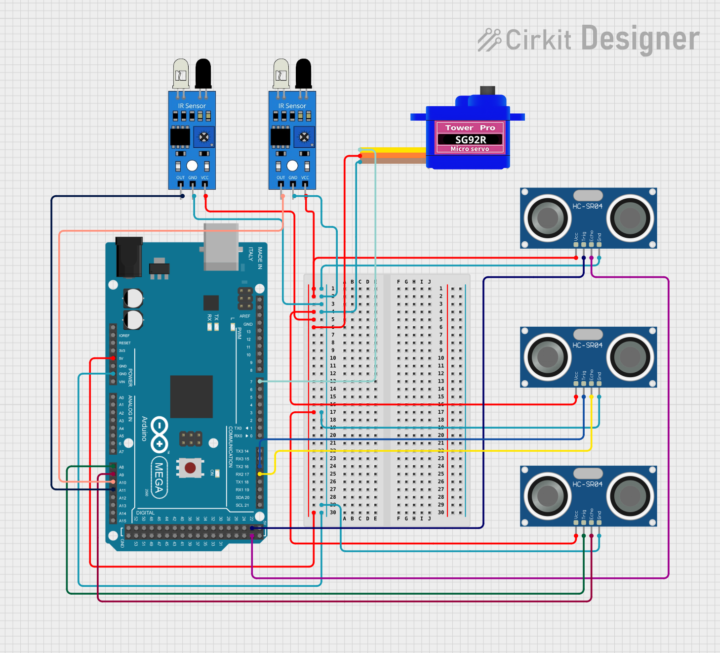
Circuit Documentation
Summary of the Circuit
This circuit is designed to interface an Arduino Mega 2560 with multiple sensors including IR sensors and HC-SR04 Ultrasonic Sensors, as well as a Servomotor SG92R. The Arduino Mega 2560 serves as the central processing unit, reading sensor inputs and controlling the servomotor based on the sensor data. The IR sensors are used to detect the presence of objects, while the ultrasonic sensors measure distance by emitting ultrasonic waves and timing how long it takes for the echo to return. The servomotor is controlled by the Arduino and can be used to move parts of the system based on the sensor inputs.
Component List
Arduino Mega 2560
- Microcontroller board based on the ATmega2560
- Provides numerous digital input/output pins, analog inputs, and other peripherals
IR Sensors
- Used for object detection
- Typically consists of an IR transmitter and receiver
HC-SR04 Ultrasonic Sensors
- Used for measuring distances using ultrasonic sound waves
- Consists of a transmitter (TRIG) and an echo receiver (ECHO)
Servomotor SG92R
- A small and lightweight servo motor
- Capable of precise control of angular position
Wiring Details
Arduino Mega 2560
- 5V pin is connected to the VCC pins of all IR sensors, HC-SR04 Ultrasonic Sensors, and the Servomotor SG92R to provide power.
- GND pin is connected to the GND pins of all IR sensors, HC-SR04 Ultrasonic Sensors, and the Servomotor SG92R to complete the power circuit.
- A8 pin is connected to the TRIG pin of one HC-SR04 Ultrasonic Sensor.
- A9 pin is connected to the ECHO pin of the same HC-SR04 Ultrasonic Sensor.
- A10 pin is connected to the OUT pin of one IR sensor.
- A11 pin is connected to the OUT pin of another IR sensor.
- D17 PWM/RX2 pin is connected to the ECHO pin of another HC-SR04 Ultrasonic Sensor.
- D16 PWM/TX2 pin is connected to the TRIG pin of the same HC-SR04 Ultrasonic Sensor.
- D7 PWM pin is connected to the SIG pin of the Servomotor SG92R.
- D22 pin is connected to the TRIG pin of another HC-SR04 Ultrasonic Sensor.
- D23 pin is connected to the ECHO pin of the same HC-SR04 Ultrasonic Sensor.
IR Sensors
- VCC pin is connected to the 5V power supply from the Arduino.
- GND pin is connected to the ground on the Arduino.
- OUT pin is connected to an analog input on the Arduino to read sensor output.
HC-SR04 Ultrasonic Sensors
- VCC pin is connected to the 5V power supply from the Arduino.
- GND pin is connected to the ground on the Arduino.
- TRIG pin is connected to a digital output on the Arduino to initiate the ultrasonic pulse.
- ECHO pin is connected to a digital input on the Arduino to read the return signal.
Servomotor SG92R
- VCC pin is connected to the 5V power supply from the Arduino.
- GND pin is connected to the ground on the Arduino.
- SIG pin is connected to a PWM-capable digital output on the Arduino to control the motor position.
Documented Code
void setup() {
  // put your setup code here, to run once:

}

void loop() {
  // put your main code here, to run repeatedly:

}
The provided code is a template with empty setup() and loop() functions. The setup() function is intended for initialization code that runs once when the system starts, such as configuring pin modes. The loop() function contains the main logic of the program, which runs repeatedly as long as the system is powered.
For this circuit, the setup() function would typically be used to initialize the pins connected to the TRIG and ECHO pins of the ultrasonic sensors as output and input, respectively, and to set the pin mode for the IR sensor outputs and servomotor control pin. The loop() function would contain the logic to read the sensor values, process them, and control the servomotor accordingly.
Please note that the actual implementation code for the sensors and servomotor control is not provided and would need to be written based on the specific requirements of the application.