
ESP32-Based Wi-Fi Connected Temperature and Humidity Monitor
View and Edit Project In Cirkit Designer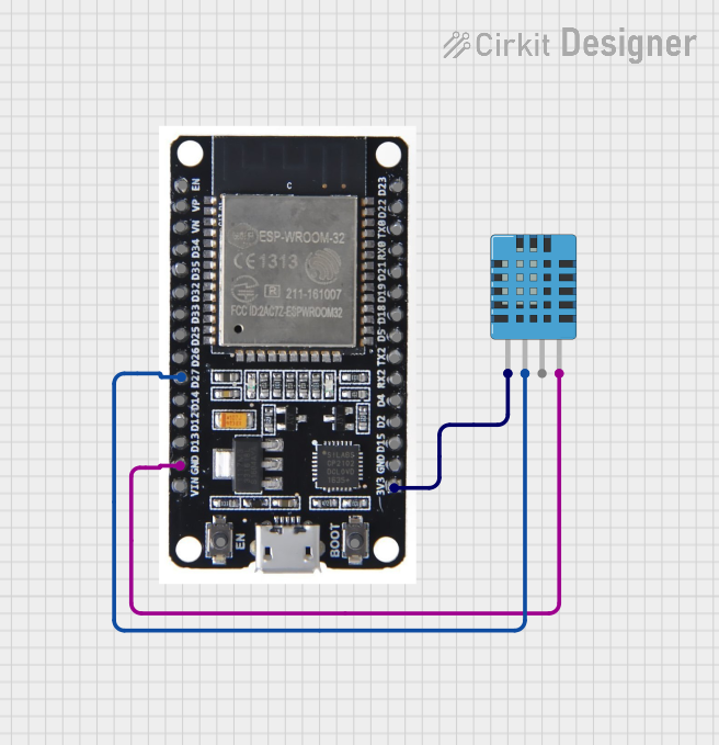
Circuit Documentation
Summary
This document provides a detailed overview of a circuit that includes an ESP32 microcontroller and a DHT11 Humidity and Temperature Sensor. The ESP32 is used to read data from the DHT11 sensor. The circuit is powered by the 3.3V output from the ESP32, and the ground connections are shared between the components.
Component List
ESP32
- Description: A powerful microcontroller with integrated Wi-Fi and Bluetooth capabilities.
- Pins: EN, VP, VN, D34, D35, D32, D33, D25, D26, D27, D14, D12, D13, GND, VIN, 3V3, D15, D2, D4, RX2, TX2, D5, D18, D19, D21, RX0, TX0, D22, D23, BOOT
- Purpose in Circuit: Acts as the main controller, reading data from the DHT11 sensor and potentially processing or transmitting it.
DHT11 Humidity and Temperature Sensor
- Description: A basic, low-cost digital temperature and humidity sensor.
- Pins: VDD, DATA, NULL, GND
- Purpose in Circuit: Measures the ambient temperature and humidity and sends the data to the ESP32.
Wiring Details
ESP32
- Pin D27: Connected to the DATA pin of the DHT11 sensor.
- Pin GND: Connected to the GND pin of the DHT11 sensor.
- Pin 3V3: Connected to the VDD pin of the DHT11 sensor.
DHT11 Humidity and Temperature Sensor
- Pin DATA: Connected to the D27 pin of the ESP32.
- Pin GND: Connected to the GND pin of the ESP32.
- Pin VDD: Connected to the 3V3 pin of the ESP32.
Documented Code
There is no code provided for this circuit. If code is added in the future, it should be documented here with explanations of its functionality and how it interacts with the hardware components.
This document provides a comprehensive overview of the circuit, including the components used, their connections, and the purpose of each component in the circuit.