
Arduino Nano-Based Panic Button System with GPS and GSM Modules
View and Edit Project In Cirkit Designer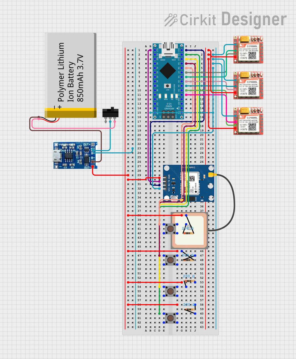
Circuit Documentation
Summary of the Circuit
The circuit is designed to operate as a panic button system, utilizing an Arduino Nano as the central microcontroller. It interfaces with a NEO6MV2 GPS module to obtain location data and three SIM800L GSM modules to communicate with external services such as hospital, fire department, and police. The system includes four pushbuttons that trigger different actions: three are dedicated to calling specific hotline numbers, and one is used to send the GPS location. A slide switch is used to control the power supply from a lithium battery, which is charged via a charging module. The circuit is designed to handle simultaneous button presses, allowing for the GPS location to be sent along with the hotline call.
Component List
Arduino Nano
- Microcontroller board based on the ATmega328P
- It has a variety of digital and analog I/O pins.
GPS NEO 6M
- A GPS module that provides location data.
Pushbutton (x4)
- Simple on/off switch that controls a circuit.
Resistor (x4)
- A 200 Ohm resistor used for current limiting or pull-up/pull-down configurations.
lipo battery charger module
- A module used for charging lithium polymer batteries.
Polymer Lithium Ion Battery - 850mAh
- A rechargeable battery that provides power to the circuit.
SIM800L (x3)
- GSM/GPRS modules used for cellular communication.
Toggle Switch
- A switch that can connect or disconnect the circuit it controls.
Wiring Details
Arduino Nano
D13/SCKconnected to GPS NEO 6M TXD12/MISOconnected to GPS NEO 6M RXD11/MOSIconnected to Pushbutton (GPS button)D10connected to Pushbutton (Police hotline button)D9connected to Pushbutton (Fire department hotline button)D8connected to Pushbutton (Hospital hotline button)D7connected to SIM800L (Hospital) TXDD6connected to SIM800L (Hospital) RXDD5connected to SIM800L (Fire department) TXDD4connected to SIM800L (Fire department) RXDD3connected to SIM800L (Police) TXDD2connected to SIM800L (Police) RXDVINconnected to the positive voltage supply net (VCC)
GPS NEO 6M
VCCconnected to the positive voltage supply net (VCC)GNDconnected to the ground net
Pushbuttons
- Each pushbutton has one pin connected to an Arduino Nano digital pin (D8, D9, D10, D11)
- The other pin of each pushbutton is connected to one side of a 200 Ohm resistor, whose other side is connected to the ground net
Resistor (x4)
- Each 200 Ohm resistor is connected between a pushbutton and the ground net
lipo battery charger module
B+connected to the positive side of the Polymer Lithium Ion BatteryB-connected to the negative side of the Polymer Lithium Ion BatteryOUT-connected to the ground net
Polymer Lithium Ion Battery - 850mAh
VCCconnected to the Toggle Switch L2GNDconnected to the ground net
SIM800L (x3)
- Each SIM800L module has its
VCCconnected to the positive voltage supply net (VCC) - Each SIM800L module has its
GNDconnected to the ground net - Each SIM800L module has its
TXDandRXDconnected to corresponding Arduino Nano digital pins
Toggle Switch
COMconnected to the positive side of the Polymer Lithium Ion BatteryL2connected to the positive voltage supply net (VCC)
Documented Code
/*
 * Panic Button System
 * This Arduino sketch controls a panic button system with an Arduino Nano,
 * NEO6MV2 GPS module, 3 SIM800L GSM modules, 4 panic buttons, a slide switch,
 * a lithium battery, and a charging module. The first three buttons are
 * connected to each GSM module to call specific hotline numbers (hospital,
 * fire department, police). The fourth button sends the GPS location. If a
 * hotline button and the GPS button are pressed simultaneously, the GPS
 * location is sent to the corresponding hotline number.
 */

#include <SoftwareSerial.h>

// Define pins for buttons
const int button1Pin = 8; // Hospital
const int button2Pin = 9; // Fire Department
const int button3Pin = 10; // Police
const int button4Pin = 11; // GPS

// Define pins for GSM modules
const int gsm1RxPin = 6;
const int gsm1TxPin = 7;
const int gsm2RxPin = 4;
const int gsm2TxPin = 5;
const int gsm3RxPin = 2;
const int gsm3TxPin = 3;

// Define pins for GPS module
const int gpsRxPin = 12;
const int gpsTxPin = 13;

// Create SoftwareSerial objects for GSM modules
SoftwareSerial gsm1(gsm1RxPin, gsm1TxPin);
SoftwareSerial gsm2(gsm2RxPin, gsm2TxPin);
SoftwareSerial gsm3(gsm3RxPin, gsm3TxPin);

// Create SoftwareSerial object for GPS module
SoftwareSerial gps(gpsRxPin, gpsTxPin);

void setup() {
  // Initialize serial communication
  Serial.begin(9600);
  gsm1.begin(9600);
  gsm2.begin(9600);
  gsm3.begin(9600);
  gps.begin(9600);

  // Initialize button pins as inputs
  pinMode(button1Pin, INPUT);
  pinMode(button2Pin, INPUT);
  pinMode(button3Pin, INPUT);
  pinMode(button4Pin, INPUT);
}

void loop() {
  // Read button states
  bool button1State = digitalRead(button1Pin);
  bool button2State = digitalRead(button2Pin);
  bool button3State = digitalRead(button3Pin);
  bool button4State = digitalRead(button4Pin);

  // Check if any button is pressed
  if (button1State) {
    callHotline(gsm1, "hospital");
    if (button4State) {
      sendGPSLocation(gsm1);
    }
  } else if (button2State) {
    callHotline(gsm2, "fire department");
    if (button4State) {
      sendGPSLocation(gsm2);
    }
  } else if (button3State) {
    callHotline(gsm3, "police");
    if (button4State) {
      sendGPSLocation(gsm3);
    }
  } else if (button4State) {
    sendGPSLocation(gsm1); // Default to hospital if only GPS button is pressed
  }
}

void callHotline(SoftwareSerial &gsm, const char *hotline) {
  Serial.print("Calling ");
  Serial.println(hotline);

  // Dial the hotline number using the GSM module
  if (strcmp(hotline, "hospital") == 0) {
    gsm.print("+639066353525;\r"); // Replace with the actual hospital number
  } else if (strcmp(hotline, "fire department") == 0) {
    gsm.print("+639286294539;\r"); // Replace with the actual fire department number
  } else if (strcmp(hotline, "police") == 0) {
    gsm.print("+639060244955;\r"); // Replace with the actual police number
  }
}

void sendGPSLocation(SoftwareSerial &gsm) {
  Serial.println("Sending GPS location...");

  // Buffer to store GPS data
  char gpsData[100];
  int index = 0;

  // Read data from GPS module
  while (gps.available()) {
    char c = gps.read();
    if (c == '\n') {
      break;
    }
    gpsData[index++] = c;
  }
  gpsData[index] = '\0'; // Null-terminate the string

  // Send GPS data via GSM module
  gsm.print("AT+CMGF=1\r"); // Set SMS mode to text
  delay(100);
  gsm.print("AT+CMGS=\"+1234567890\"\r"); // Replace with the recipient's phone number
  delay(100);
  gsm.print("GPS Location: ");
  gsm.print(gpsData);
  delay(100);
  gsm.write(26); // ASCII code for CTRL+Z to send the SMS
  delay(100);
}
This code is responsible for the operation of the panic button system. It initializes the communication with the GSM and GPS modules, reads the state of the buttons, and performs actions such as calling hotlines or sending GPS location based on button presses. The callHotline function dials a predefined number, and the sendGPSLocation function reads GPS data and sends it via SMS.