Cirkit Designer
Your all-in-one circuit design IDE
Home /
Project Documentation
Arduino UNO-Based Security System with Bluetooth Connectivity and LED Indicators

Circuit Documentation
Summary
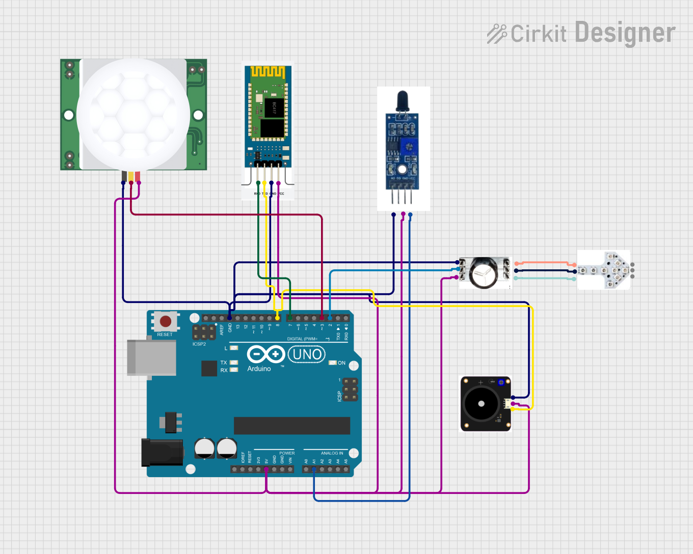
This document provides a detailed overview of a circuit that includes an Arduino UNO as the central microcontroller, interfaced with various sensors and modules including a PIR motion sensor (HC-SR501), a buzzer (FIT0449), a soil moisture sensor (SEN040129), a Bluetooth module (HC-06), and two LED modules (JLED-START and JLED-ARROW-9). The circuit is designed to perform tasks that likely involve motion detection, wireless communication, and visual signaling.
Component List
Arduino UNO
- Description: A microcontroller board based on the ATmega328P.
- Pins: UNUSED, IOREF, Reset, 3.3V, 5V, GND, Vin, A0-A5, SCL, SDA, AREF, D0-D13.
PIR HC-SR501
- Description: A passive infrared sensor module for motion detection.
- Pins: VDD, SIG, GND.
FIT0449
- Description: A buzzer module for audible signaling.
- Pins: GND, SIGNAL, VCC.
SEN040129
- Description: A soil moisture sensor for detecting the moisture level in soil.
- Pins: GND, VCC, OUT.
HC-06
- Description: A Bluetooth module for wireless communication.
- Pins: RXD, TXD, GND, VCC.
JLED-ARROW-9
- Description: An LED module with an arrow pattern for directional indication.
- Pins: DOUT, VCC, GND, DIN.
JLED-START
- Description: An LED module for visual signaling.
- Pins: GND, DIN, VCC, DOUT.
Wiring Details
Arduino UNO
- 5V connected to VCC of FIT0449, PIR HC-SR501, JLED-START, HC-06, SEN040129.
- GND connected to GND of FIT0449, PIR HC-SR501, JLED-START, HC-06, SEN040129.
- A1 connected to OUT of SEN040129.
- D8 connected to SIGNAL of FIT0449 and TXD of HC-06.
- D7 connected to RXD of HC-06.
- D3 connected to SIG of PIR HC-SR501.
- D2 connected to DIN of JLED-START.
PIR HC-SR501
- VDD connected to 5V of Arduino UNO.
- SIG connected to D3 of Arduino UNO.
- GND connected to GND of Arduino UNO.
FIT0449
- VCC connected to 5V of Arduino UNO.
- SIGNAL connected to D8 of Arduino UNO.
- GND connected to GND of Arduino UNO.
SEN040129
- VCC connected to 5V of Arduino UNO.
- OUT connected to A1 of Arduino UNO.
- GND connected to GND of Arduino UNO.
HC-06
- VCC connected to 5V of Arduino UNO.
- TXD connected to D8 of Arduino UNO.
- RXD connected to D7 of Arduino UNO.
- GND connected to GND of Arduino UNO.
JLED-ARROW-9
- DIN connected to DOUT of JLED-START.
- VCC connected to VCC of JLED-START.
- GND connected to GND of JLED-START.
JLED-START
- DIN connected to D2 of Arduino UNO.
- VCC connected to 5V of Arduino UNO.
- GND connected to GND of Arduino UNO.
- DOUT connected to DIN of JLED-ARROW-9.
Documented Code
Arduino UNO Code (sketch.ino)
void setup() {
  // put your setup code here, to run once:

}

void loop() {
  // put your main code here, to run repeatedly:

}
Note: The provided code is a template and does not contain any functional code. It needs to be populated with the logic to control the sensors and modules based on the requirements of the circuit's application.